72 of 132
M-SV-001-EN Rev.E
Compressor Components
3.13.3 Verification
3.13.3.1 IGV Stepper
Motor Verification
1. Isolate compressor power.
2. Disconnect the compressor controller cable
from the suction pressure/temperature sensor
and the IGV Motor power feed through. See
Figure 67 (IGV Connections).
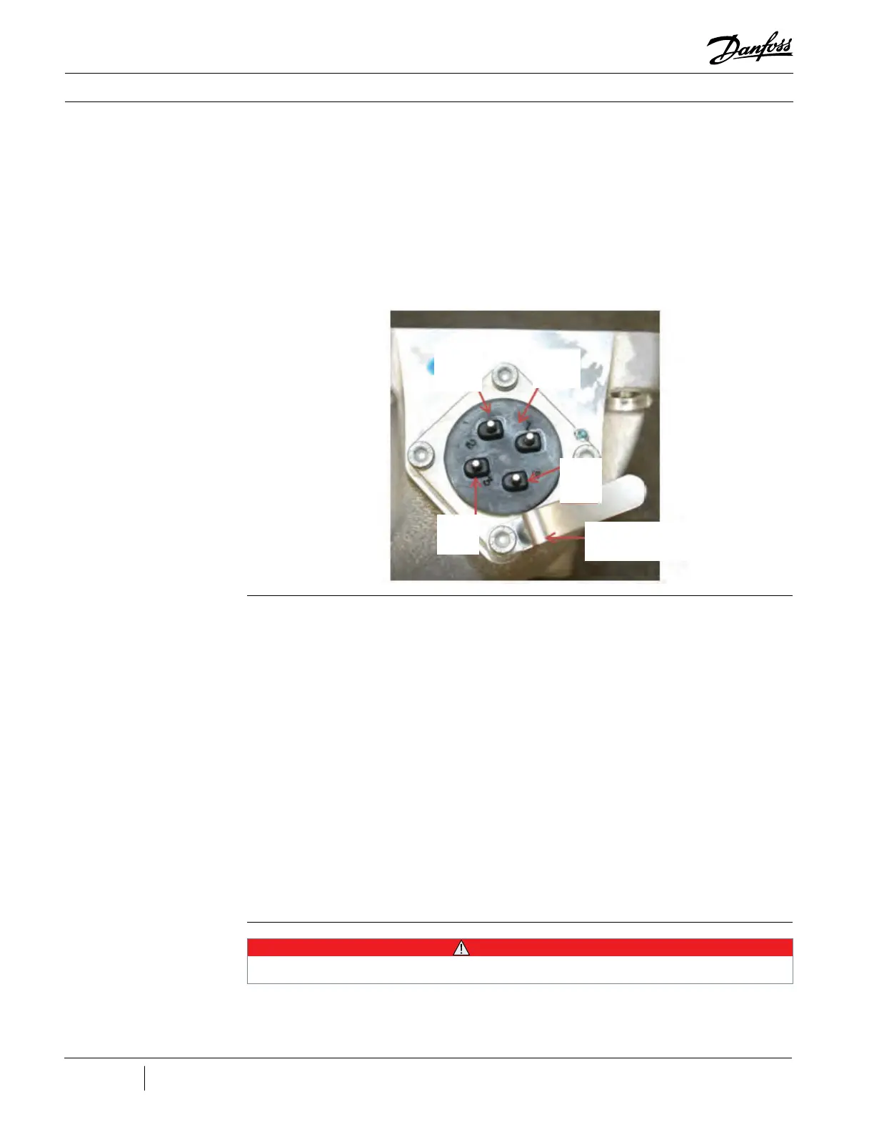
3. Measure the resistance between terminals 1
and 2, and 3 and 4 of the IGV Motor feed through.
The measured value should be between 46Ω and
59Ω. See Figure 68 (IGV Motor Feed Through).
4. Measure the resistance between the IGV Motor
feed through terminals and the IGV Housing. The
measured value should be open or infinity.
Figure 68 - IGV Motor Feed
Through
3.13.3.2 IGV Operation
Verification
3.13.4 Removal and
Installation
1. Remove the Service Side Cover.
2. Open the Service Monitor Tool (SMT)
installed on your computer and connect to the
compressor.
3. Open the Compressor Configuration tool.
Set the Compressor Control Mode to Manual
Control by selecting Manual Control from the
Compressor Control Mode drop-down list.
4. Open the Compressor Monitor tool.
5. In the IGV Open Percentage parameter box,
input 110%.
6. On the Backplane, there are four LEDs that
should light up when the IGV Motor is being
driven. See Figure 61 (LED Locations).
• Check that all four LEDs are blinking and that
the IGV position indicator moves toward open.
See Figure 67 (IGV Connections).
7. In the IGV Open Percentage parameter box,
input 0%.
8. Check that all four LEDs are blinking and that
the IGV position indicator moves toward closed.
See Figure 67 (IGV Connections).
9. Measure the +15V test point on the Backplane
to verify voltage is supplied to the Serial Driver
for the IGV.
• • • CAUTION • • •
Removal of the IGV mounting screws will release refrigerant. Isolation and recovery of the refrigerant must be performed by a
qualified service technician adhering to industry/ASHRAE standards.
1
2
3
4
Cable Clip
 Loading...


