5-1
VLT is a registered Danfoss trademark
INTRODUCTION
WARNING
!
Touching electrical parts of drive may be fatal
even after equipment has been disconnected
from AC power. Wait 20 minutes for D-frame sizes
or 40 minutes for E-frame sizes after power has
been removed before touching any internal
components to ensure that capacitors have fully
discharged.
This section contains detailed procedures for testing VLT drives.
Previous sections of this manual provide symptoms, alarms
and other conditions which require additional test procedures
to further diagnose the drive. The results of these tests indicate
the appropriate repair actions. Again, because the drive
monitors input and output signals, motor conditions, AC and
DC power and other functions, the source of fault conditions
may exist outside of the drive itself. Testing described here will
isolate many of these conditions as well. Sections 6 and 7,
Disassembly and Assembly Instructions, describes detailed
procedures for removing and replacing drive components, as
required (D- or E-sized drives, respectively).
Drive testing is divided into 5.1 Static Tests, 5.2 Dynamic Tests,
and 5.3 Initial Start Up or After Repair Drive Tests. Static tests
are conducted without power applied to the drive. Most drive
problems can be diagnosed simply with these tests. Static
tests are performed with little or no disassembly. The purpose
of static testing is to check for shorted power components.
Perform these tests on any unit suspected of containing faulty
power components prior to applying power.
WARNING
!
For dynamic test procedures, main input power is
required. All line powered devices and power
supplies are energized at rated voltage. Use
extreme caution when conducting tests on a
powered drive. Contact with powered components
could result in electrical shock and personal injury.
Dynamic tests are performed with power applied to the drive.
Dynamic testing traces signal circuitry to isolate faulty
components.
Both D-frame and E-frame size drives (see Introduction Section)
are covered here. Differences in the procedures are noted, as
required. However, the Soft Charge and Rectifier Circuit Test,
Soft Charge Rectifier Test, and Fan Continuity Test sections
are independent for D-frame and E-frame drives.
SECTION 5
TEST PROCEDURES
Signal Test Board
The signal test board can be used to test circuitry within the
drive and provides easy access to test points. The test board
plugs into connector MK104 on the interface card. Its use is
described in the procedures where called out. See Section 8,
Signal Test Board, for detailed pin descriptions.
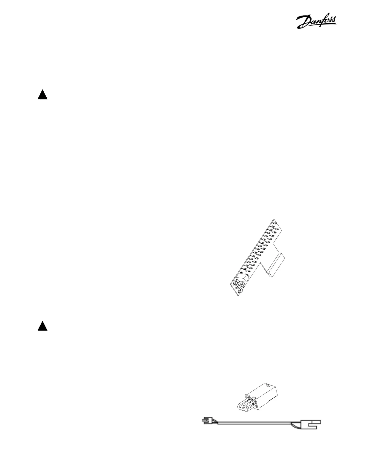
Signal Test Board
Test Cable
The test cable bypasses the main DC bus and supplies DC
voltage to the power card from the soft charge card. This
provides voltage for testing the power card without the drive
circuitry being powered. The SCR shorting plug ensures that
the SCRs do not fire. The cable connects between the soft
charge connector MK3 and the power card connector MK105.
Test Cable Connector and SCR Shorting Plug
Replace any defective component and retest the drive with
the new component before applying power to the drive as
described in 5.3 Initial Start Up or After Repair Drive Tests.
TOOLS REQUIRED FOR TESTING
Digital volt/ohm meter capable of reading real RMS
Analog volt meter
Oscilloscope
Clamp-on style ammeter
Signal test board p/n 176F8437
Test cable p/n 176F8439