4-7
VLT is a registered Danfoss trademark
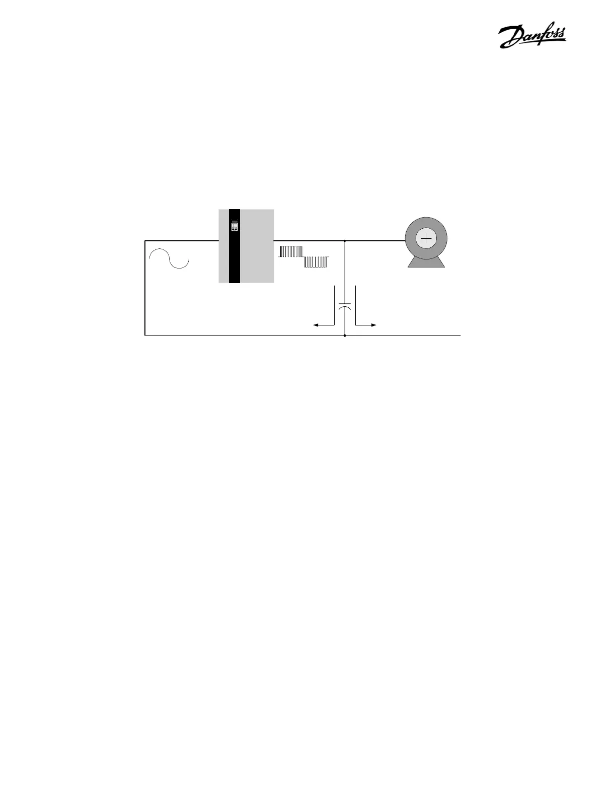
Signal conductors are especially vulnerable when they are
run parallel to the power conductors for any distance. EMI
coupled into these conductors can affect either the drive
or the interconnected control device. See Figure 4-4.
While these currents will tend to travel back to the drive,
imperfections in the system will cause some current to flow
in undesirable paths thus exposing other locations to the
EMI.
VLT
AC Line Motor cable
VFD
Motor
Stray capacitance
AC Line
Figure 4-4. Alternate Signal Conductor Currents
HF currents can be coupled into the AC line supplying the drive when the
AC line conductors are located close to the motor cables.
Preventative Measures
EMI related problems are more effectively alleviated during
the design and installation phases rather then after the
system is in service. Many of the steps listed here can be
implemented at a relatively low cost when compared to
the cost to later identify and fix the problem in the field.
Grounding. The drive and motor should be solidly grounded
to the equipment frame. A good HF connection is necessary
to allow the HF currents to return back to the drive rather
than to travel thorough the power network. The ground
connection will be ineffective if it has high impedance to
HF currents, therefore it should be as short and direct as
practical. Flat braided cable has lower HF impedance than
round cable. Simply mounting the drive or motor onto a
painted surface will not create an effective ground
connection. In addition, running a separate ground
conductor directly between the drive and the driven motor
is recommended.
Cable routing. Avoid routing motor wiring, AC line wiring,
and signal wiring in parallel. If parallel routing is unavoidable,
try to maintain a separation of 6 - 8 inches between the
cables or separate them with a grounded conductive
partition. Avoid routing cables through free air.
Signal cable selection. Single conductor 600 volt rated
wires provide the least protection from EMI. Twisted-pair
and shielded twist-pair cables are available which are
specifically designed to minimize the effects of EMI. While
unshielded twisted-pair cables are often adequate, shielded
twisted-pair cables provide another degree of protection.
The signal cable’s shield should be terminated in a manner
that is appropriate for the connected equipment. Avoid
terminating the shield through a pigtail connection as this
increases the HF impedance and spoils the effectiveness
of the shield. Refer to Section 1, Grounding Shielded Cables.
A simple alternative is to twist the existing single conductors
to provide a balanced capacitive and inductive coupling
thus canceling out differential-mode interference. While not
as effective as true twisted-pair cable, it can be
implemented in the field using the materials on hand.