5-5
VLT is a registered Danfoss trademark
5.1.2 Soft Charge Rectifier Test: D-frame
Size
Testing the soft charge rectifier requires access to the soft
charge card connectors. It requires removing the control card
and power card mounting plate. Refer to removal instructions
for soft charge card in Section 6.
Do not remove the soft charge card completely or unplug any
connectors not called out. Doing so will break the continuity
path of these measurements and may result in a false
interpretation of a failure.
1. Extract soft charge card far enough to access
connectors.
2. Disconnect DC cable at connector MK3.
Since the rectifier test requires the soft charge resistor to be in
the circuit, verify the resistor is good before proceeding.
3. Measure resistance between pins A and B of
connector MK4 on soft charge card. It should
read 27 ohms (±10%) for 380 - 500V drives and
68 ohms (±10%) for 525 - 690V. A reading
outside this range indicates a defective soft
charge resistor. Replace resistor in accordance
with disassembly procedures in Section 6.
Continue tests.
Should the resistor be defective and a replacement not readily
available, the remainder of the tests can be carried out by
disconnecting the cable at connector MK4 on the soft charge
card and placing a temporary jumper across pins A and B.
This provides a path for continuity for the remaining tests. Ensure
any temporary jumpers are removed at the conclusion of the
tests.
For the following tests, set the meter to diode check or Rx100
scale.
4. Connect negative (-) meter lead to positive (+)
MK3 (A) (DC output to DC bus), and connect
positive (+) meter lead to MK1 terminals R, S,
and T in turn. Each reading should show a diode
drop.
An incorrect reading here indicates the soft charge rectifier is
shorted. The rectifier is not serviced as a component. Replace
the entire soft charge card in accordance with the disassembly
procedures in Section 6.
5. Reverse meter leads with positive (+) meter lead
to positive (+) MK3 (A). Connect negative (-) lead
to MK1 terminals R, S, and T in turn. Each
reading should show open.
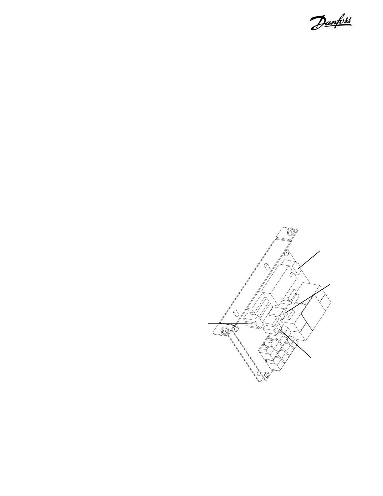
Figure 5-3. Soft Charge Card Connectors
6. Connect positive (+) meter lead to negative (-)
MK3 (C). Connect negative (-) meter lead to
MK1 terminals R, S, and T in turn. Each reading
should show a diode drop.
An incorrect reading here indicates the soft charge rectifier is
shorted. The rectifier is not serviced as a component. Replace
the entire soft charge card in accordance with the disassembly
procedures in Section 6.
7. Reverse meter leads with negative (-) meter lead
to negative (-) MK3 (C). Connect positive (+)
meter lead to MK1 terminals R, S, and T in turn.
Each reading should show open.
If all tests indicate correctly while isolating between the SCR/
Diode modules and the soft charge card, the SCR/Diode
modules are suspect. Before reconnecting the cable at MK3,
return to the Main Rectifier tests and repeat those tests. Put
the power card temporarily back in place to retest the main
rectifier. Replace any defective assemblies in accordance with
the disassembly procedures in Section 6.
MK1
MK2
MK4
MK3