5-17
VLT is a registered Danfoss trademark
5.2.6 Input Waveform Test
Testing the current waveform on the input of the drive can
assist in troubleshooting mains phase loss conditions or
suspected problems with the SCR/Diode modules. Phase loss
caused by the AC supply can be easily detected. In addition,
the rectifier section is controlled by SCR/Diode modules. Should
one of the SCR/Diode modules become defective or the gate
signal to the SCR lost, the drive will respond the same as loss
of one of the phases.
The following measurements require an oscilloscope with
voltage and current probes.
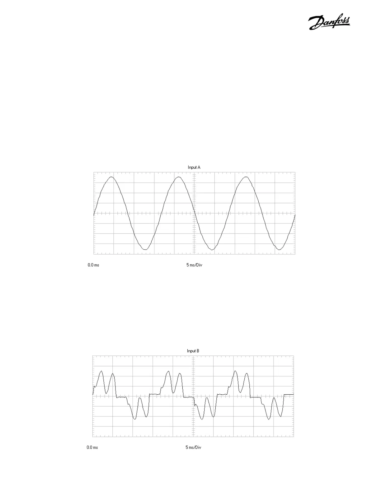
Under normal operating conditions, the waveform of a single
phase of input AC voltage to the drive appears as in Figure 5-9.
Figure 5-9. Normal AC Input Voltage Waveform
The waveform shown in Figure 5-10 represents the input current
waveform for the same phase as Figure 5-9 while the drive is
running at 40% load. The two positive and two negative jumps
are typical of any 6 diode bridge. It is the same for drives with
SCR/Diode modules.
Figure 5-10. AC Input Current Waveform with Diode Bridge
CONTINUED ON NEXT PAGE