5-2
VLT is a registered Danfoss trademark
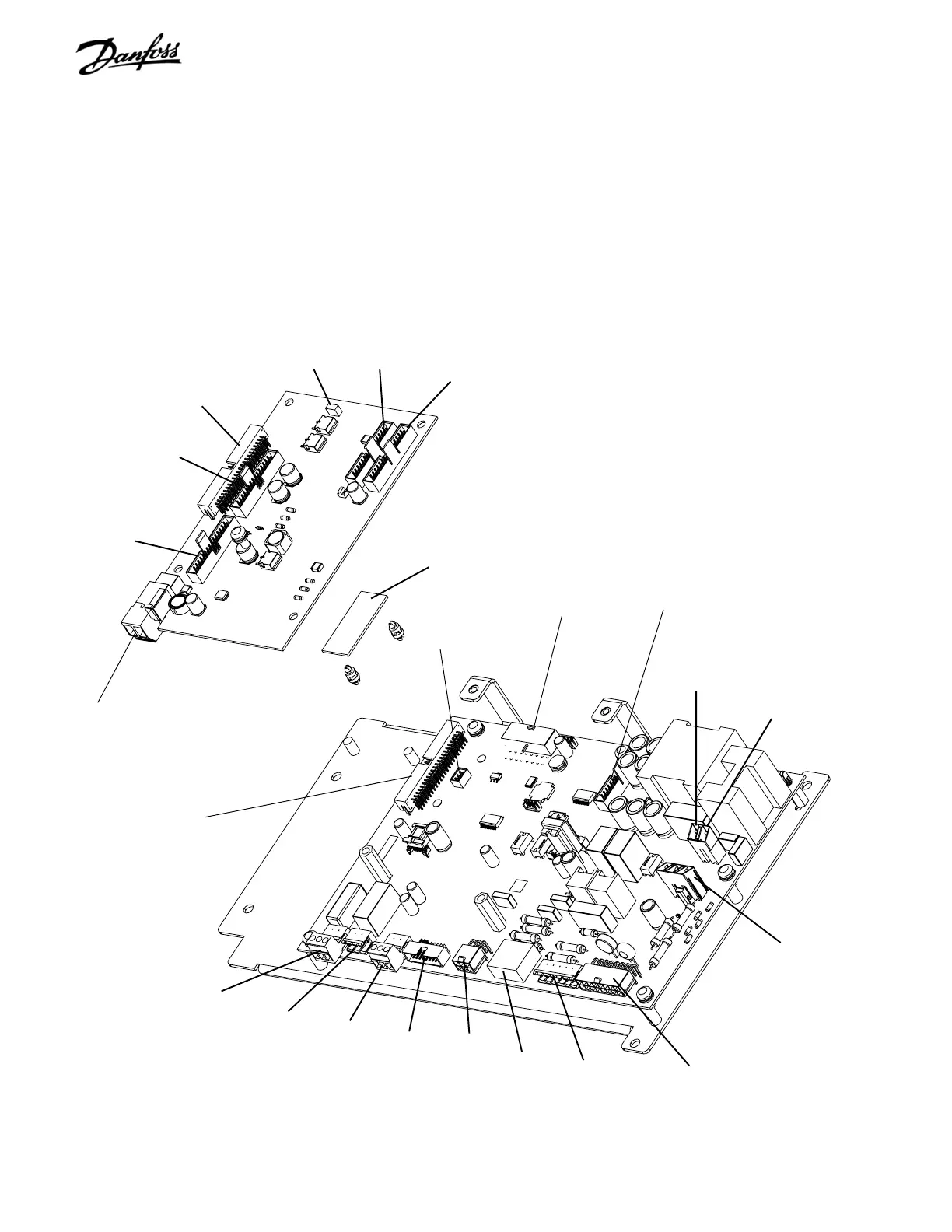
Figure 5-1. Interface PCA and Power PCA Connector Identification
MK101
MK105
MK100
Interface Card
MK104
MK102
MK103
Power Card
MK105(B) -DC
MK400
MK107
FK103
MK100
MK106
MK109
FK102
FK101
FK100
MK105(A) +DC
Current scaling card
5.0 TEST PROCEDURES
5.1 STATIC TEST PROCEDURES
All tests should be made with a meter capable of testing diodes.
Use a digital volt/ohm meter (VOM) set on the diode scale or
an analog ohmmeter set on Rx100 scale. Before making any
checks disconnect all input, motor and brake resistor
connections.
Figure 5-1. Interface PCA and Power Card PCA Connector
Identification is provided as a reference for finding the
appropriate connectors described in the test procedures in
this section. Some connectors are optional and not on all drive
configurations.
NOTE
For best troubleshooting results, it is
recommended that static test procedures
described in this section be performed in the
order presented.
Diode Drop. A diode drop reading will vary depending on the
model of ohmmeter. Whatever the ohmmeter displays as a
typical forward bias diode is defined as a "diode drop" in these
procedures. With a typical DVM, the voltage drop across most
components will be around .300 to .500. The opposite reading
is referred to as infinity and most DMVs will display the value
OL for overload.
MK110
MK111
MK102
MK104
FK100