2-3
VLT is a registered Danfoss trademark
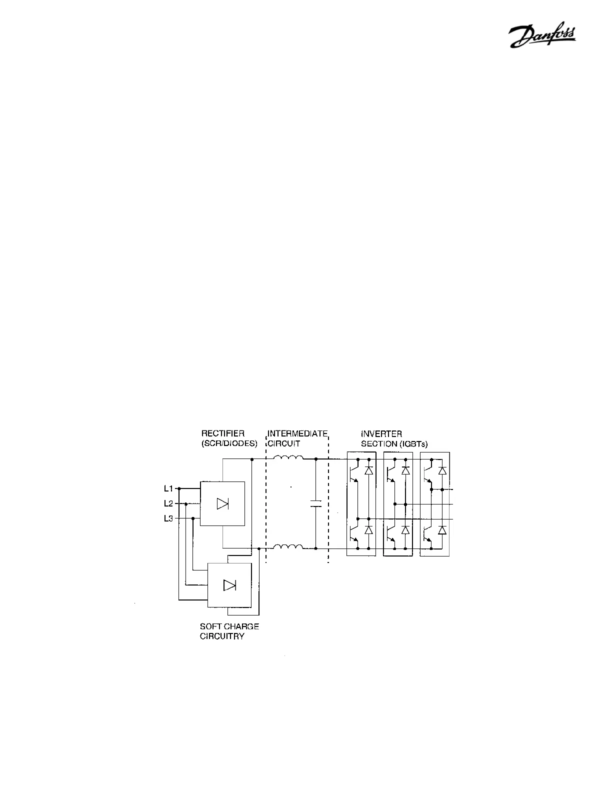
Power Section
The high voltage power section consists of AC input terminals,
AC and DC bus bars, fusing, harnessing, AC output, and
optional components. The power section (see Figure 2-3) also
contains circuitry for the soft charge and SCR/Diode modules
in the rectifier; the DC bus filter circuitry containing the DC
coils, often referred to as the intermediate or DC bus circuit;
and the output IGBT modules which make up the inverter
section.
In conjunction with the SCR/Diode modules, the soft charge
circuit limits the inrush current when power is first applied and
the DC bus capacitors are charging. This is accomplished by
the SCRs in the modules being held off while charging current
passes through the soft charge resistors, thereby limiting the
current. The DC bus circuitry smoothes the pulsating DC
voltage created by the conversion from the AC supply.
The DC coil is a single unit with two coils wound on a common
core. One coil resides in the positive side of the DC bus and
the other in the negative. The coil aids in the reduction of line
harmonics.
The DC bus capacitors are arranged into a capacitor bank
along with bleeder and balancing circuitry. Due to the
requirement for higher power capacity, some drives have two
capacitor banks connected in parallel.
Figure 2-3. Typical Power Section
The inverter section is made up of six IGBTs, commonly referred
to as switches. One switch is necessary for each half phase
of the three-phase power, for a total of six. The six IGBTs are
contained in a single module. Due to higher current handling
requirements, some models contain two or three larger six-
pack style modules. In these units, each switch (half phase)
is made up of two or three IGBTs in parallel.
A Hall effect type current sensor is located on each phase of
the output to measure motor current. This type of device is
used instead of more common current transformer (CT)
devices in order to reduce the amount of frequency and phase
distortion that CTs introduce into the signal. With Hall sensors,
the average, peak, and ground leakage currents can be
monitored.
T1
T2
T3