Synchronizing controller
MG.10.N4.02 - VLT is a registered Danfoss trademark 9
Encoder monitor
Both encoder interfaces are equipped with a monitoring circuit that can detect open circuit as well as
short circuit of each encoder channel. Each encoder channel has a LED showing the status: Green
light means ok, no light means fault. Zero channel monitoring can be switched off by means of switch
1.4, this is necessary when using incremental encoders without Zero channel or absolute encoders.
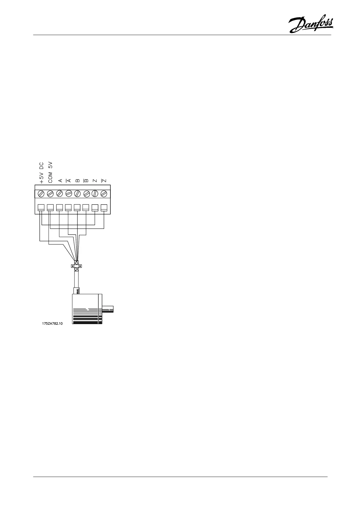
Switch 1.4 disables monitoring of both master and slave Zero channel. If disabling of only one of the
two Zero channels is required (e.g. when using incremental master encoder and absolute slave
encoder) the unused Zero channel input must be connected to 5V/common as shown below.
An encoder fault will only result in an ”Option error” 92 if encoder monitoring is activated via parameter 713
(master) and 711 (slave).
Note: Monitoring of the master encoder is disabled when switch 1.3 is ”OFF”.