Synchronizing controller
10 MG.10.N4.02 - VLT is a registered Danfoss trademark
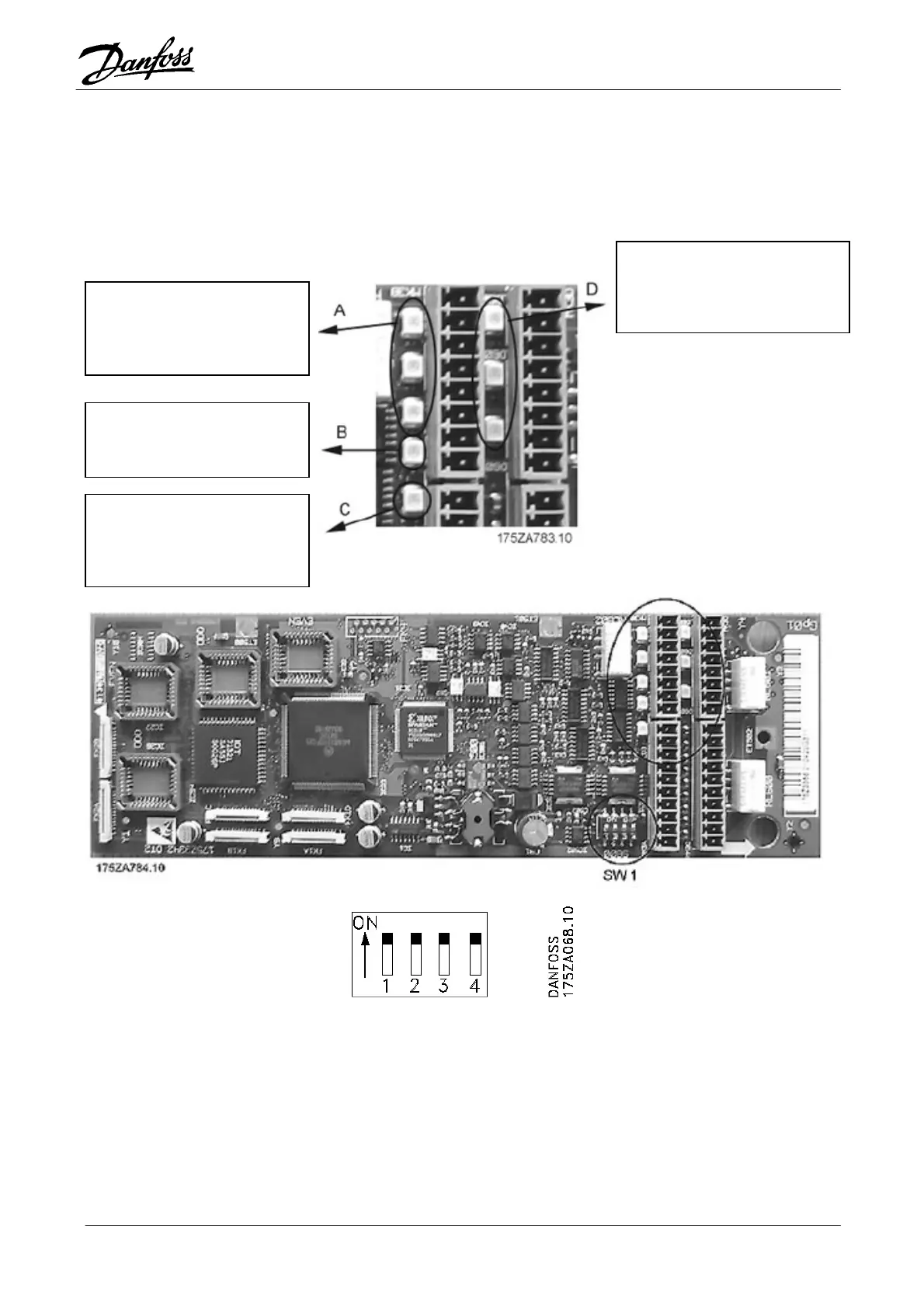
Encoder monitor master,
channel A, B and Z:
LED off = Short or open
circuit
Encoder monitor slave,
channel A, B and Z:
LED off = Short or open circuit
LED green = Ok
.
Option card layout
Option card layout showing the position of connectors and dip switch.
SW 1.1: Connect(ON)/disconnect(OFF) 24 V from control card (see description of supply voltages).
SW 1.2: Connect(ON)/disconnect(OFF) 24 V common from control card.
SW 1.3: Connect(ON)/disconnect(OFF) termination resistor for master encoder (see description of virtual
master function).
Note: When OFF the master encoder monitor is disabled.
SW 1.4: Switch Z-channel encoder monitor ON/OFF for both master and slave.
Default setting of switch 1.1. - 1.4 is ON.
5V monitor:
LED off = no 5V
D Green = 5V ok.
CPU monitor:
LED must flash at 1 Hz to
indicate a running CPU
s
stem