EasyManuals Logo

Danfoss VLT 5000 User Manual

Danfoss VLT 5000
88 pages
To Next Page IconTo Next Page
To Previous Page IconTo Previous Page
Page #83 background imageLoading...
Page #83 background image
Synchronizing controller
82 MG.10.N4.02 - VLT is a registered Danfoss trademark
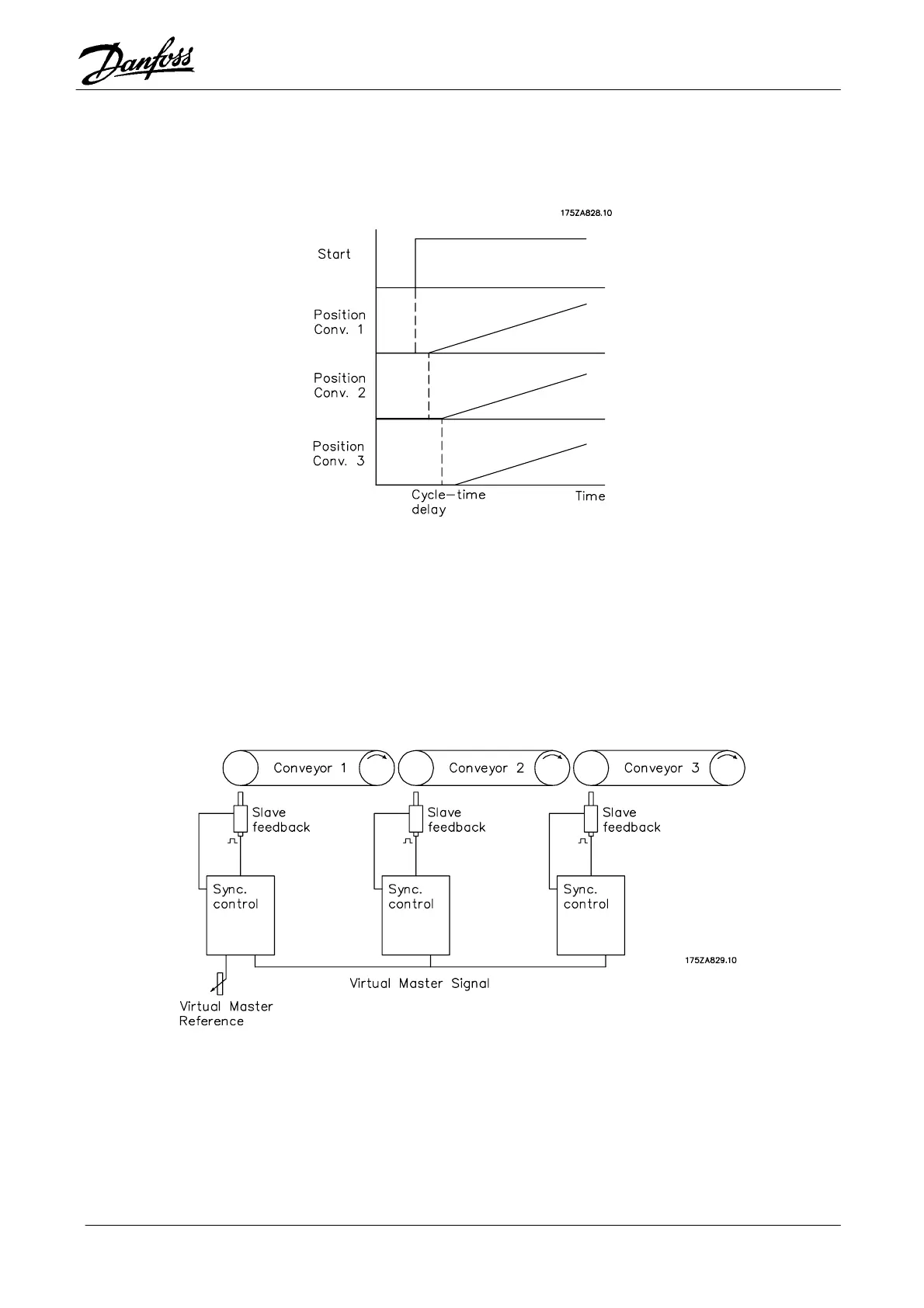
As can be seen from the diagram below, at Start, as well as with every change in
speed of the master drive, the cycle times are added; they are then compensated
for again based on the control characteristics of the controller in question.
Figure 30: Addition of the cycle times
In this case, the same application is realised by means incorporating a virtual
master. Although the way that the reference value is introduced at the first
belt is analogous, the value is used to set the virtual master signals.
Figure 31: Synchronization with virtual master

Table of Contents

Other manuals for Danfoss VLT 5000

Questions and Answers:

Question and Answer IconNeed help?

Do you have a question about the Danfoss VLT 5000 and is the answer not in the manual?

Danfoss VLT 5000 Specifications

General IconGeneral
Frequency50/60 Hz
Output Voltage Range0-100% of input voltage
Protection FeaturesOvervoltage, Undervoltage, Overtemperature, Short circuit
Communication InterfacesRS-485
Ambient Temperature Range-10°C to +40°C
Enclosure RatingIP20, IP21, IP55
Input Voltage200-240V AC, 380-480V AC, 525-600V AC

Related product manuals