Synchronizing controller
MG.10.N4.02 - VLT is a registered Danfoss trademark 13
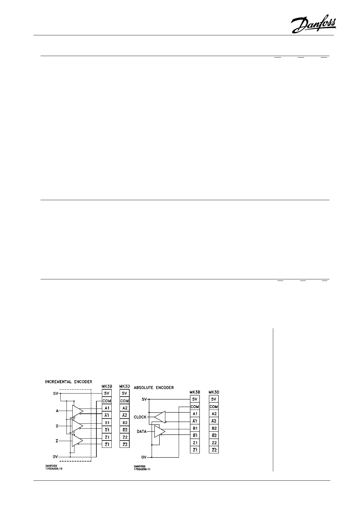
Encoder input 2, MK3D (slave):
Terminal designations ......................................................................................... A2, A2, B2, B2 , Z2, Z2
Incremental:
Signal level ...........................................................................................................................5 V differential
Signal type......................................................................................................................Linedriver, RS422
Input impedance................................................................................................................................120 Ω
Maximum frequency......................................................................................220 kHz (at 50 % duty cycle)
Phase displacement between A and B..........................................................................................90° ±30°
Absolute:
Signal level ...........................................................................................................................5 V differential
Signal type.............................................................................................................................................SSI
Protocol ...................................................................................................................................... Gray code
Data length .........................................................................................................................................25 bit
Parity....................................................................................................................................................none
Clock frequency.................................................................................................................. 105 or 260 kHz
Maximum positions per revolution.......................................................................................................8192
Maximum number of revolutions .........................................................................................................4096
Encoder cable:
Cable type...Twisted pair and screened. Note: Please observe the prescriptions of the encoder supplier
Cable length.................................................................Observe the prescriptions of the encoder supplier.
Absolute encoder is tested ok up to 150 meter cable at 105 kHz clock and 100 m at 260 kHz clock.
(Tested with TR electronic encoder type CE-65 M 8192*4096 and appropriate cable prescribed by TR
electronic.)
Maximum allowed time delay between clock and data signal measured at the controller terminals...........
................................................................................................................................ 105 kHz clock = 9µsec
............................................................................................................................ 260 kHz clock = 3.5 µsec
Encoder output, MK3B:
Terminal designations ........................................................................................... A1, A1, B1, B1, Z1, Z1
Signal type......................................................................................................................Linedriver, RS485
Maximum frequency...................................................................................................................... 150 kHz
Minimum frequency......................................................................................................................... 150 Hz
Maximum number of slaves .....................................................................31 (more when using repeaters)
Maximum cable length.......................................................................................................................400 m