14
VLT is a registered Danfoss trademark
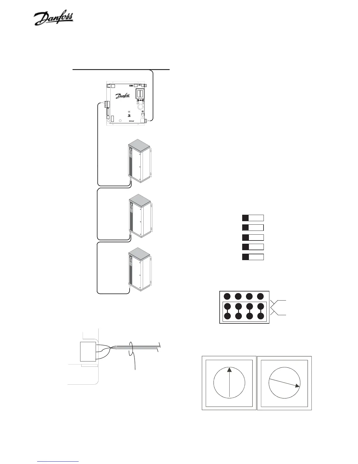
Shield
Net -
Net +
ARC156 Network
Port 1
ARCnet network connection
Figure 13. Port 2 Configuration Jumper Settings
Figure 11. ARCnet Network Connection
Figure 12. BACLink DIP Switches
Procedure
1. Switch BACLink portal power off.
2. Wire ARCnet network input cable to BACLink port1 (see
Figure 11).
3. Set port 1 DIP switch to ARC156 (see Figure 12).
4. Plug EIA-485/232 configuration jumper to EIA-485 position
as shown in Figure 13.
5. Set portal device instance number using rotary address
switches (see Figure 14).
6. Set BACLink portal address DIP switch. BACLink portal
DIP switch 5 (refer back to Figure 1) must correspond to
device instance number setting. Set switch to +0 for
addresses 0to 99 or to +100 for addresses 100 to199.
7. Wire to drives from BACLink port 2 from Net (+) to drive
terminal 68 and Net (-) to drive terminal 69.
1
2
3
4
IP Address
Switch 2
Port 1
Off/ On
Default/ Assigned
Portal Address
+0/+100
ARC156/ Other
Off/On
5
Switch 1
EIA-485
EIA-232
ARCnet
VLT
®
BACLink
™
ARCnet
EIA-485
NOTE: EIA-485 Net+
and Net- from Port 2
to drive input terminals
68 (+) and 69 (-)
NOTE: Terminate shield at only
one portal of a multiportal
network.
0
1
2
3
4
5
6
7
8
9
0
1
2
3
4
5
6
7
8
9
10's digit
1's digit
Figure 14. Rotary Address Switches

 Loading...


