VLT
®
6000 HVAC
5
MG.60.G2.02 - VLT is a registered Danfoss Trademark
■■
■■
■ Programming the VLT 6000
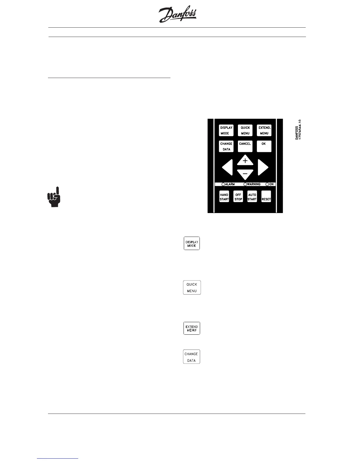
Parameter Change Keys
The LCP keys are divided into groups by function.
The keys above indicator lamps are used for
parameter setup, selecting the display indication
during normal operation, and controlling the drive
speed during local speed control operation.
The keys below the indicator lamps are used for
Start/Stop control, selection of the operating
location, and reset.
FigurFigur
FigurFigur
Figur
e 1 e 1
e 1 e 1
e 1 VLT 6000 Keypad
The DISPLAY MODE key is used to
change a display mode or to return
to the Display Mode from either the
Quick Menu or the Extend Menu
mode.
The QUICK MENU key gives access
to the parameters available for the
Quick Menu setup. Parameters in
this menu are the 12 most important
setup parameters for the drive.
The EXTEND.MENU key gives
access to all parameters.
The CHANGE DATA key is used for
changing the value of a selected
parameter. To change data, the
desired parameter is first selected. The
CHANGE DATA key is then pressed to
enable editing of the parameter. An
underline in the display will move under
the parameter‘s value to show that it is
being edited.
Trademarks
FLN
®
is a Siemens registered trademark.
VLT
®
is a Danfoss registered trademark.
The VLT 6000 frequency converter is delivered for
installation and setup with the required applica-tion
parameters already programmed at the factory.
Specific motor nameplate data may have to be
entered at the time of setup. The instructions in this
section are intended to provide a general under-
standing of programming procedures and to enter
Quick Menu setup data. See the VLT 6000
Operating Instructions for detailed information.
NOTE:NOTE:
NOTE:NOTE:
NOTE:
Quick menu data for commissioning drive
cannot be entered via FLN serial bus.
Control Panel
The Local Control Panel (LCP), see Figure 1, is a
complete interface for programming and operating
the drive. The control panel can be removed from
the drive and installed up to 3 meters (10 feet) away
using the remote mounting kit.
The control panel has five functions:
- Display
- Keys for changing the display
- Keys for changing programming parameters
- Keys for controlling drive operation
- Indicator lamps
The LCP uses a four-line, alpha-numeric LCD
display. The display can show four operating data
values and three operating condition values
continuously. During programming, all the information
required for quick, effective parameter setup of the
drive is displayed. All drive parameters can be
changed from the control panel. Three lamps indicate
power on (ON), warning (WARNING) and
alarm (ALARM).