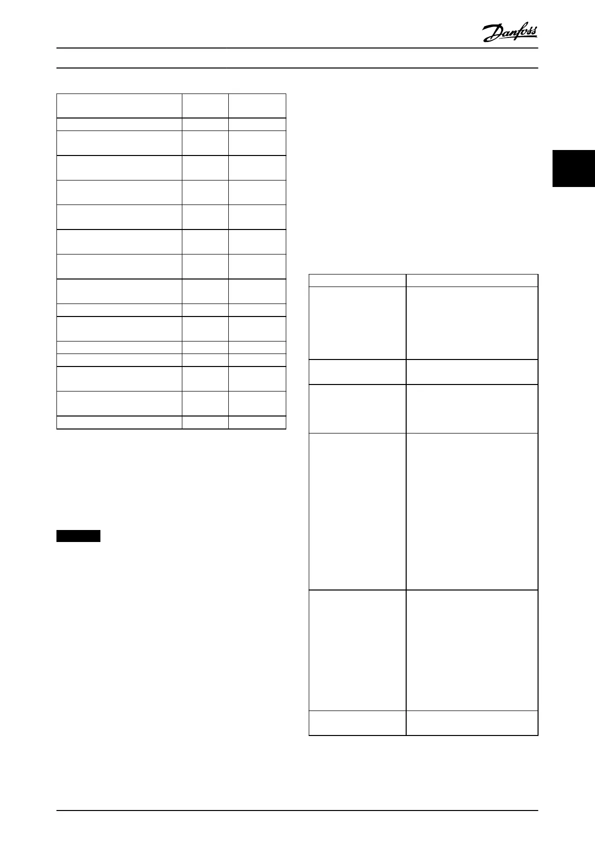
Parameter 1-10 Motor
Construction
[0]
Asynchron
[1] PM Motor
non salient
Parameter 2-17 Over-voltage Control
x
Parameter 4-10 Motor Speed
Direction
x x
Parameter 4-11 Motor Speed Low
Limit [RPM]
x x
Parameter 4-12 Motor Speed Low
Limit [Hz]
x x
Parameter 4-13 Motor Speed High
Limit [RPM]
x x
Parameter 4-14 Motor Speed High
Limit [Hz]
x x
Parameter 4-16 Torque Limit Motor
Mode
x x
Parameter 4-17 Torque Limit
Generator Mode
x x
Parameter 4-18 Current Limit
x x
Parameter 4-19 Max Output
Frequency
x x
4-58 Missing Motor Phase Function
x
Parameter 14-40 VT Level
x
Parameter 14-41 AEO Minimum
Magnetisation
x
Parameter 14-42 Minimum AEO
Frequency
x
Parameter 14-43 Motor Cosphi
x
Table 3.4 Motor Selection Parameter
3.3.3
SynRM Motor Set-up with VVC
+
This section describes how to set up a SynRM motor with
VVC
+
.
NOTICE
The SmartStart wizard covers the basic conguration of
SynRM motors.
Initial programming steps
To activate SynRM motor operation, select [5] Sync.
Reluctance in 1-10 Motor Construction.
Programming motor data
After performing the initial programming steps, the SynRM
motor-related parameters in parameter groups 1-2* Motor
Data, 1-3* Adv. Motor Data, and 1-4* Adv. Motor Data II are
active. Use the motor nameplate data and the motor
datasheet to programme the following parameters in the
order listed:
•
1-23 Motor Frequency.
•
1-24 Motor Current.
•
1-25 Motor Nominal Speed.
•
1-26 Motor Cont. Rated Torque.
Run a complete AMA using
1-29 Automatic Motor
Adaptation (AMA) [1] Enable Complete AMA or enter the
following parameters manually:
•
1-30 Stator Resistance (Rs).
•
1-37 d-axis Inductance (Ld).
•
1-44 d-axis Inductance Sat. (LdSat).
•
1-45 q-axis Inductance Sat. (LqSat).
•
1-48 Inductance Sat. Point.
Application-specic adjustments
Start the motor at nominal speed. If the application does
not run well, check the VVC
+
SynRM settings. Table 3.5
provides application-specic recommendations:
Application Settings
Low-inertia applications
I
Load
/I
Motor
<5
Increase parameter 1-17 Voltage lter
time const. by factor 5 to 10.
Reduce parameter 1-14 Damping
Gain.
Reduce parameter 1-66 Min. Current
at Low Speed (<100%).
Low-inertia applications
50>I
Load
/I
Motor
>5
Keep the default values.
High-inertia applications
I
Load
/I
Motor
> 50
Increase parameter 1-14 Damping
Gain, 1-15 Low Speed Filter Time
Const., and 1-16 High Speed Filter
Time Const.
High-load at low speed
<30% (rated speed)
Increase parameter 1-17 Voltage lter
time const.
Increase parameter 1-66 Min. Current
at Low Speed to adjust the starting
torque. 100% current provides
nominal torque as starting torque.
This parameter is independent of
30-20 High Starting Torque Time [s]
and 30-21 High Starting Torque
Current [%]). Working at a current
level higher than 100% for a
prolonged time can cause the motor
to overheat.
Dynamic applications
Increase 14-41 AEO Minimum
Magnetisation for highly dynamic
applications. Adjusting 14-41 AEO
Minimum Magnetisation ensures a
good balance between energy
eciency and dynamics. Adjust
14-42 Minimum AEO Frequency to
specify the minimum frequency at
which the frequency converter
should use minimum magnetisation.
Motor sizes less than 18
kW
Avoid short ramp-down times.
Table 3.5 Recommendations for Various Applications
If the motor starts oscillating at a certain speed, increase
1-14 Damping Gain. Increase the damping gain value in
Parameter Descriptions
Programming Guide
MG11CE02 Danfoss A/S © 03/2015 All rights reserved. 39
3 3
 Loading...


