2-10 Brake Function
Option: Function:
Available selections depend on
parameter 1-10 Motor Construction:
[0] Asynchron:
[0] o
[1] Resistor brake
[2] AS brake
[1] PM non-salient:
[0]
o
[1] Resistor brake
[0] O No brake resistor installed.
[1] Resistor
brake
Brake resistor incorporated in the system, for
dissipation of surplus braking energy as heat.
Connecting a brake resistor allows a higher DC
link voltage during braking (generating operation).
The resistor brake function is only active in
adjustable frequency drives with an integral
dynamic brake.
[2] AC brake AC Brake will only work in Compressor Torque
mode in parameter 1-03 Torque Characteristics.
2-17 Over-voltage Control
Option: Function:
[0] Disabled No OVC required.
[2] * Enabled Activates OVC.
NOTICE!
Parameter 2-17 Over-voltage Control will not have eect
when parameter 1-10 Motor Construction = [1] PM, non-
salient SPM.
NOTICE!
The ramp time is automatically adjusted to avoid
tripping of the adjustable frequency drive.
3-02 Minimum Reference
Range: Function:
Size
related*
[ -999999.999 -
par. 3-03
ReferenceFeed-
backUnit]
Enter the Minimum Reference. The
Minimum Reference is the lowest
value obtainable by summing all
references. The Minimum Reference
value and unit matches the cong-
uration choice made in
parameter 1-00
Conguration Mode
and parameter 20-12 Reference/
Feedback Unit, respectively.
NOTICE!
This parameter is used in
open-loop only.
3-04 Reference Function
Option: Function:
[0] Sum Sums both external and preset reference
sources.
[1] External/
Preset
Use either the preset or the external reference
source.
Shift between external and preset via a
command on a digital input.
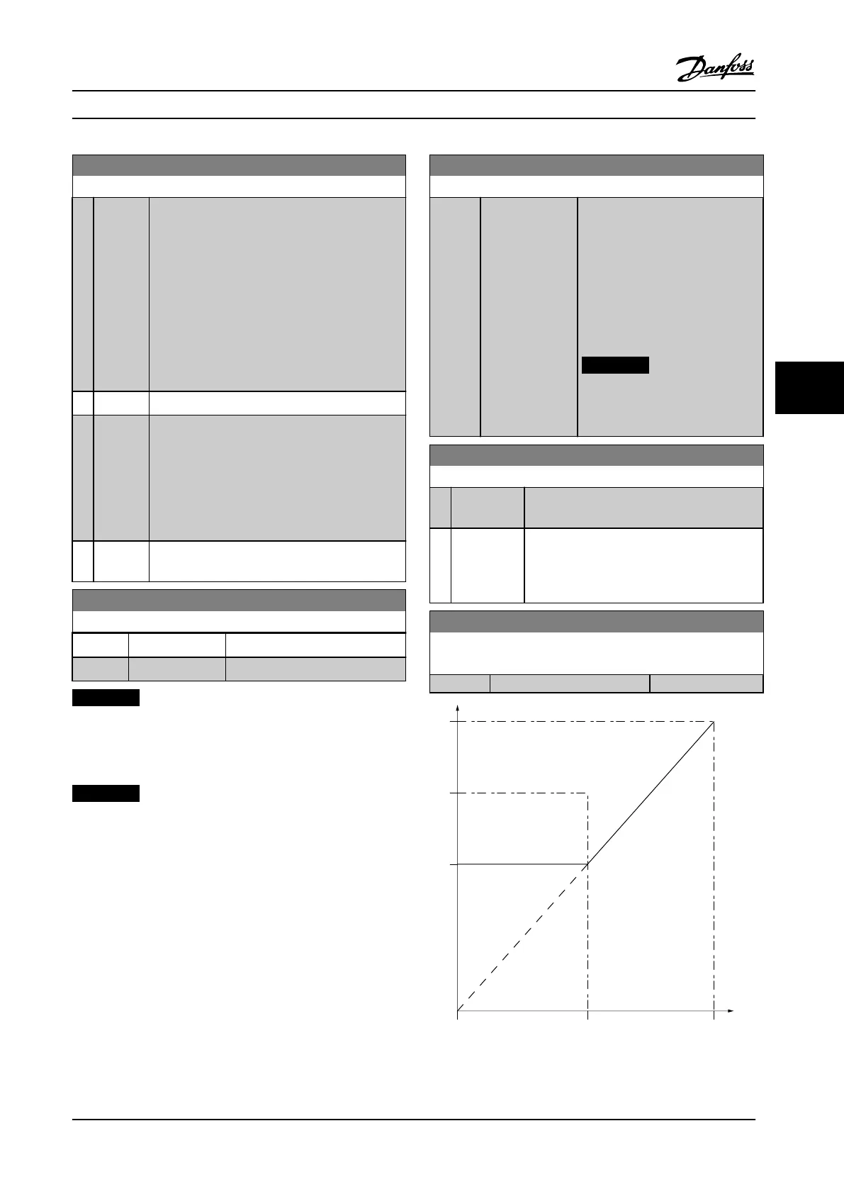
3-10 Preset Reference
Array [8]
Range: Function:
0 %* [-100 - 100 %]
P3-03
P3-02
0 50 100%
P3-10
130BB036.10
Figure 6.10
How to Program Instruction Manual
MG11F522 Danfoss A/S © 08/2014 All rights reserved. 91
6 6
 Loading...


