Figure 6.11
3-15 Reference 1 Source
Option: Function:
Select the reference input to be used
for the rst reference signal.
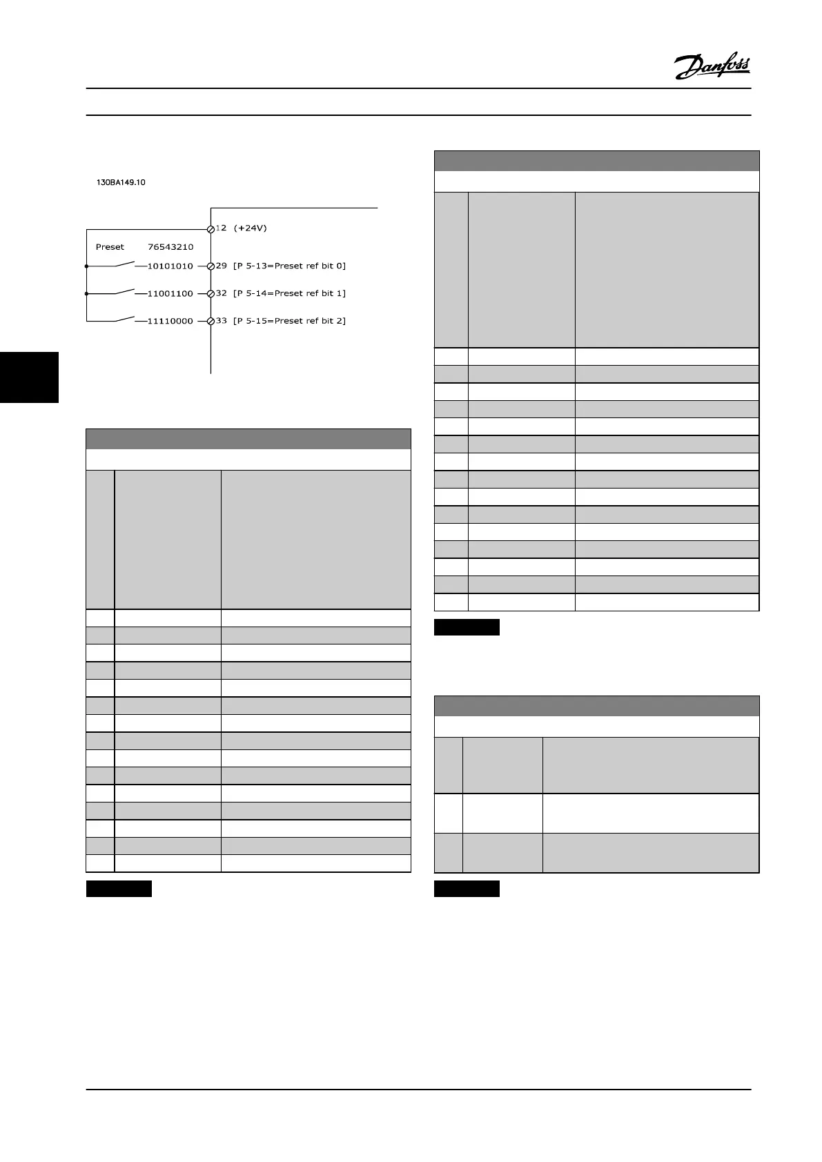
Parameter 3-15 Reference 1 Source,
parameter 3-16 Reference 2 Source and
parameter 3-17 Reference 3 Source
dene up to three dierent reference
signals. The sum of these reference
signals denes the actual reference.
[0] No function
[1] * Analog Input 53
[2] Analog Input 54
[7] Pulse input 29
[8] Pulse input 33
[20] Digital pot.meter
[21] Analog input X30/11
[22] Analog input X30/12
[23] Analog Input X42/1
[24] Analog Input X42/3
[25] Analog Input X42/5
[29] Analog Input X48/2
[30] Ext. Closed-loop 1
[31] Ext. Closed-loop 2
[32] Ext. Closed-loop 3
NOTICE!
This parameter cannot be adjusted while the motor is
running.
3-16 Reference 2 Source
Option: Function:
Select the reference input to be
used for the second reference signal.
parameter 3-15 Reference 1 Source,
parameter 3-16 Reference 2 Source
and parameter 3-17 Reference 3
Source dene up to three dierent
reference signals. The sum of these
reference signals denes the actual
reference.
[0] No function
[1] Analog Input 53
[2] Analog Input 54
[7] Pulse input 29
[8] Pulse input 33
[20] * Digital pot.meter
[21] Analog input X30/11
[22] Analog input X30/12
[23] Analog Input X42/1
[24] Analog Input X42/3
[25] Analog Input X42/5
[29] Analog Input X48/2
[30] Ext. Closed-loop 1
[31] Ext. Closed-loop 2
[32] Ext. Closed-loop 3
NOTICE!
This parameter cannot be adjusted while the motor is
running.
4-10 Motor Speed Direction
Option: Function:
Selects the motor speed direction required.
Use this parameter to prevent unwanted
reversing.
[0] Clockwise Only operation in clockwise direction is
allowed.
[2] * Both directions Operation in both clockwise and counter-
clockwise direction is allowed.
NOTICE!
The setting in parameter 4-10 Motor Speed Direction has
impact on the ying start in parameter 1-73 Flying Start.
How to Program
VLT
®
HVAC Drive FC 102
92 Danfoss A/S © 08/2014 All rights reserved. MG11F522
66
 Loading...


