The digital and analog inputs and outputs must be connected separately to the common inputs (terminal 20, 55, 39) of the adjustable frequency drive
to avoid ground currents from both groups to affect other groups. For example, switching on the digital input may disturb the analog input signal.
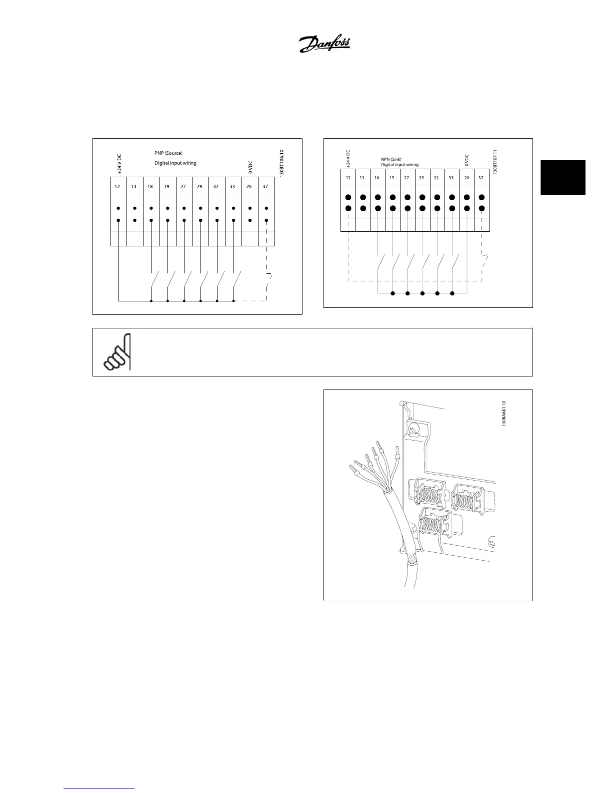
Input polarity of control terminals
NOTE!
To comply with EMC emission specifications, shielded/armored cables are recommended. If a non-shielded/unarmored cable is used,
see section
Power and Control Wiring for Non-shielded Cables
.. For more information, see
EMC Test Results
in the Design Guide.
VLT
®
AutomationDrive FC 300 Instruction
Manual
3 How to Install
MG.33.AG.22 - VLT
®
is a registered Danfoss trademark
3-25
3

 Loading...


