!
"
#
$%"
$%"
$%"
%
$%
$%
!
!
!
!
!
&!'
!
"
&!'
%
%
(
))(
&!'
%
(%*+,
(%-./!0
(0/*+&10
))(20+
3.4
5&40
2-60/
*+2.1
-60/%.2278
%6*1!5- 0
+&7-9.12.1
/07&8
/07&8
-1-/
+10/:&!0
$
$
/&,0
/04*41-/
;
;
;
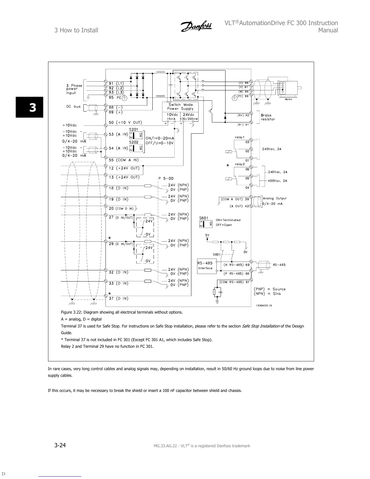
Figure 3.22: Diagram showing all electrical terminals without options.
A = analog, D = digital
Terminal 37 is used for Safe Stop. For instructions on Safe Stop installation, please refer to the section
Safe Stop Installation
of the Design
Guide.
* Terminal 37 is not included in FC 301 (Except FC 301 A1, which includes Safe Stop).
Relay 2 and Terminal 29 have no function in FC 301.
In rare cases, very long control cables and analog signals may, depending on installation, result in 50/60 Hz ground loops due to noise from line power
supply cables.
If this occurs, it may be necessary to break the shield or insert a 100 nF capacitor between shield and chassis.
3 How to Install
VLT
®
AutomationDrive FC 300 Instruction
Manual
3-24
MG.33.AG.22 - VLT
®
is a registered Danfoss trademark
3

 Loading...


