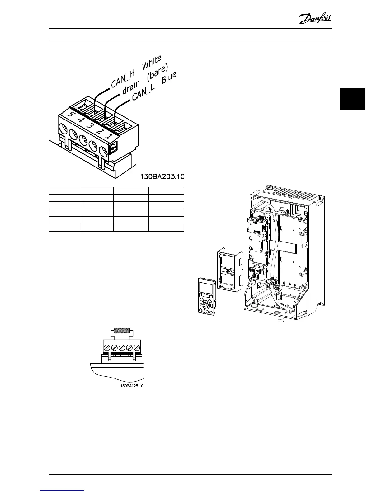
Pin no. Terminal Colour Name
1 – – Not used
2 CAN_L Blue CAN LOW
3 Drain (bare) Screen
4 CAN_H White CAN HIGH
5 – – Not used
Illustration 3.6 Fieldbus Cable Terminal Connections
CANopen termination
Install the termination resistors at each end of the bus line.
Mount the resistor between terminal 2 (CAN_L) and
terminal 4 (CAN_H).
The resistors have the following specication:
•
121 Ω
•
1% Metal
lm
•
1/4 W
Illustration 3.7 Termination Resistor Mounted
Wiring procedure for enclosure sizes A4–A5, B1–B4, and
C1–C4
1. Push the cable through cable glands.
2. Mount the eldbus connector on the eldbus
option ( CAN_L, Drain, CAN_H).
3. Prepare the eldbus cable by stripping a section
of the cable insulation. Keep the unshielded wire
as short as possible. For cable specications, refer
to chapter 3.7.1 Cable Specications.
4. Connect the eldbus cable wires to the terminals
according to the colour code of the wires, see
Illustration 3.6.
5. Fix the cable screen to the metal base plate using
cable clamp or cable tie, see Illustration 3.8.
6. Tighten cable glands securely.
Illustration 3.8 Wiring for Enclosure Sizes A4–A5, B1–B4, and
C1–C4
Installation Installation Guide
MG33J402 Danfoss A/S © 05/2015 All rights reserved. 9
3 3

 Loading...


