3 Installation
3.1 Safety Instructions
See chapter 2 Safety for general safety instructions.
3.2 EMC-compliant Installation
To obtain an EMC-compliant installation, follow the
instructions provided in the relevant frequency converter
operating instructions and design guide. Refer to the
eldbus master manual from the PLC supplier for further
installation guidelines.
3.3 Grounding
•
Ensure that all stations connected to the eldbus
network are connected to the same ground
potential. When there are long distances between
the stations in a eldbus network, connect the
individual station to the same ground potential.
Install equalising cables between the system
components.
•
Establish a grounding connection with low HF
impedance, for example by mounting the
frequency converter on a conductive back plate.
•
Keep the ground wire connections as short as
possible.
•
Establish electrical contact between the cable
screen and the frequency converter enclosure by
using metal cable glands or by using the clamps
provided on the equipment.
•
Use high-strand wire to reduce electrical
interference.
3.4
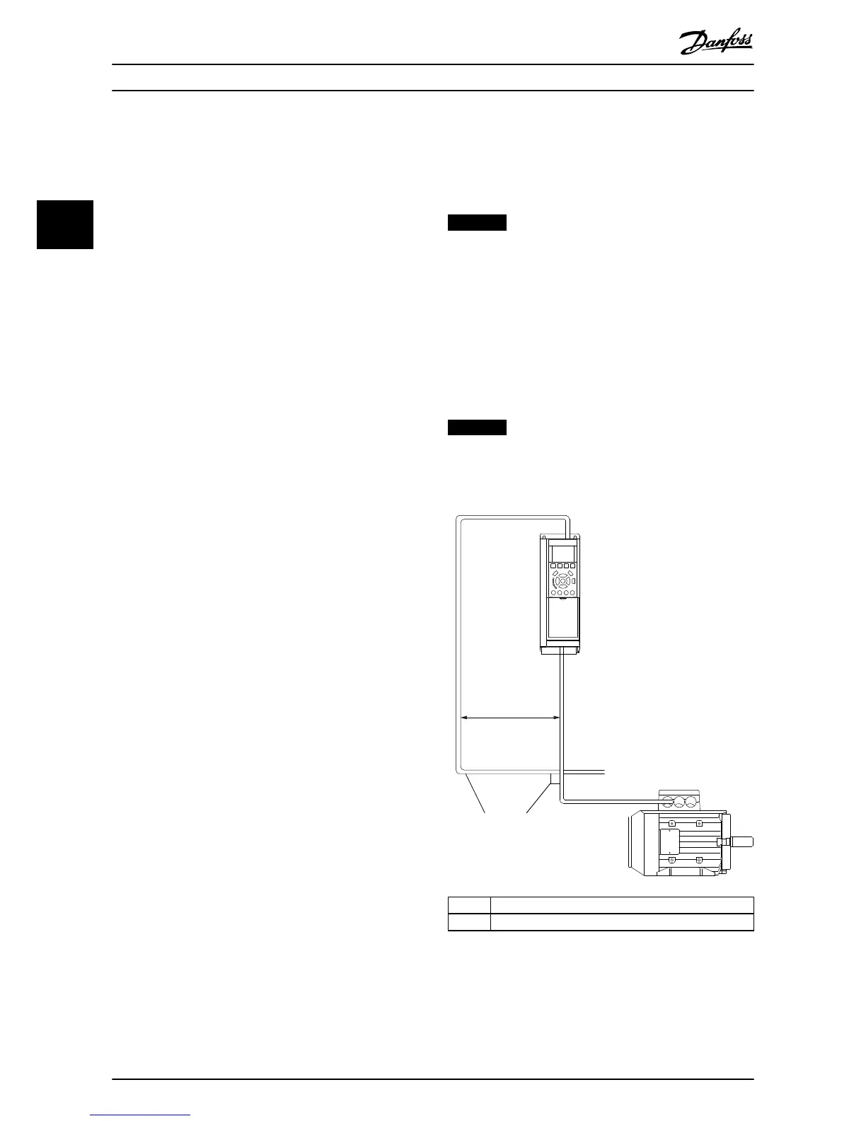
Cable Routing
NOTICE
EMC INTERFERENCE
Use screened cables for motor and control wiring, and
separate cables for eldbus communication, motor
wiring, and brake resistor. Failure to isolate eldbus
communication from motor and brake resistor cables can
result in unintended behaviour or reduced performance.
Minimum 200 mm (7.9 in) clearance between power,
motor, and control cables is required. For power sizes
above 315 kW, it is recommended to increase the
minimum distance to 500 mm (20 in).
NOTICE
When the eldbus cable crosses a motor cable or a brake
resistor cable, ensure that the cables cross at an angle of
90°.

 Loading...


