3.6 Setting Address Switches
NOTICE
Switch o the power supply before changing the address
switches. The address change comes into eect at the
next power-up.
The address switches enable setting of baudrate and node
ID:
•
Switches 8 and 7 arefor setting the baudrate for
either: 125, 250, or 500 Kbps.
•
Switches 6–1 are for setting the node address in
the range 1–62.
Switch Baudrate
8 7
On On Parameter 10-01 Bau
d Rate Select
On O 500 kbps
On On 250 kbps
On O 125 kbps
Table 3.1 Switches 8 and 7
Switch Node ID
6 5 4 3 2 1
On On On On On On Parameter
10-02 MAC
ID
On On On On On O 62
O O O O O On 1
Table 3.2 Switches 6–1
When both switch 8 and 7are set to ON, select baudrates
via parameter 10-01 Baud Rate Select: 10, 20, 50, 100, 125,
250, or 500 kbps.
When switches 6–1 are set to ON, select node ID via
parameter 10-02 MAC ID in the range: 1–127
3.7
Electrical Installation
3.7.1 Cable Specications
Baudrate
[kbps]
Maximum
cable
length [m]
Resistance
[mΩ/m]
Cable cross-
section
[mm
2
]
Termination
resistor [Ω]
500 100 <60 0.34–0.6
120
250 250
<40 0.5–0.6
125 500
50 1000
<26 0.75–0.820 2500
10 5000
Table 3.3 Cable Specications
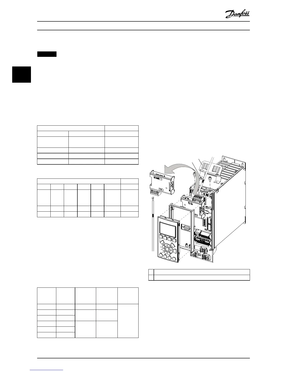
3.7.2 Wiring Procedures
Wiring procedure for enclosure sizes A1–A3
1. Mount the eldbus connector on the eldbus
option (CAN_L, Drain, CAN_H). For top cable
entry, mount the supplied EMC bracket on top of
the frequency converter with 2 screws.
2. Prepare the eldbus cable by stripping a section
of the cable insulation, so that the cable screen
contacts the EMC bracket. Keep the unshielded
wire as short as possible. For cable specications,
refer to chapter 3.7.1 Cable Specications.
3. Connect the eldbus cable wires to the terminals
according to the colour code of the wires, see
Illustration 3.6.
4. To establish mechanical xation and electrical
contact between cable screen and ground,
position the stripped cable between the spring
loaded metal clamps.

 Loading...


