FC 300 Design Guide
Introduction to FC 300
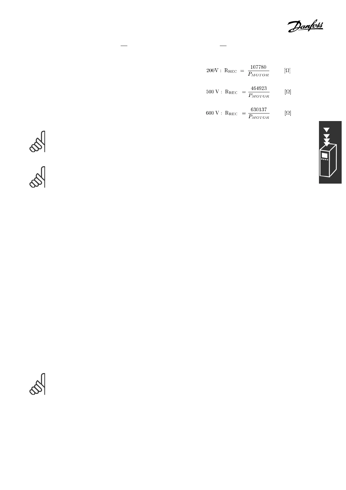
Danfoss recommends the brake resistance R
REC
,
i.e. one that guarantees that the adjustable
frequency drive is able to brake at the highest
braking torque (M
br
) of 160%.
η
motor
is typically at 0.90, while η
VLT
is
typically at 0.98.
For 200 V, 500 V, and 600 V adjus table frequency
drives, R
REC
at 160% braking torque is written as:
NOTE
The brake circuit resistance selected should not be higher than that recommende d by Danfoss.
If a brake resistor with a higher ohmic value is selected, the 160% braking torque may not be
achieved because there is a risk that the adjustable frequency drive cuts out for safety reasons.
NOTE
If a short circuit in the brake transistor occurs, power dissipation in the brake resistor is only
prevented by u sing a line switch or contactor to disconnect the AC line for the adjustable frequency
drive. (The contactor c an be controlled by the adjustable frequency drive).
" Control with Brake Fun ction
The brake is to limit the voltage in the intermediate circuit when the motor acts as a generator.
This occurs, for example, when the load drives the motor a nd the p ower accumula tes on the DC
link. The brake is built up as a chopper circuit with the connection of an external brake resistor.
Placing the brake resistor exte rnally offers the following advantages:
- The brake resistor can be selected on the basis of the application in question.
- The brake energy is d issip a ted outside the control panel, i.e. where the energy can be u tilized.
- The ele ctronics of the adjustab le frequency drive will not be overheated if the brake resistor is overloaded.
The brake is protected against short-circuiting of the brake resistor, and the brake transistor is monitore d to
ensure that short-circuiting of the transistor is detecte d. A relay/digital output can be used for protecting
the brake resistor against overloading in connection with a fault in the adjustable frequency drive.
In addition, the brake makes it possible to re a d out the momentary power and the mean power for
the latest 120 se conds. The brake can also monitor the power energizing and make sure it does
not exceed a lim it selected in par. 2-12. In p ar. 2-13, select the function to carry out when the
power transmitted to the brake resistor exceeds the limit set in par. 2-12.
Over-voltage Control (OVC) (excl. brake resistor) c an be selected as an alternative brake function in
par. 2-17. T his function is active for all units. The function ensures that a trip can be avoided if the
DC link voltage increases. This is done by increasing the output frequency to limit the voltage from
the D C link. I t is a very useful function, e.g. if the ramp-down time is too short since tripping of the
adjustable frequency drive is avoided. In this situation, the ramp-down time is extended.
NOTE
Monitoring the brake power is not a safety function; a thermal switch is required for this
purpose. The brake resistor circuit is not ground leakage protected.
49
MG.33.B3.22 - VLT is a registered Danfoss trademark

 Loading...


