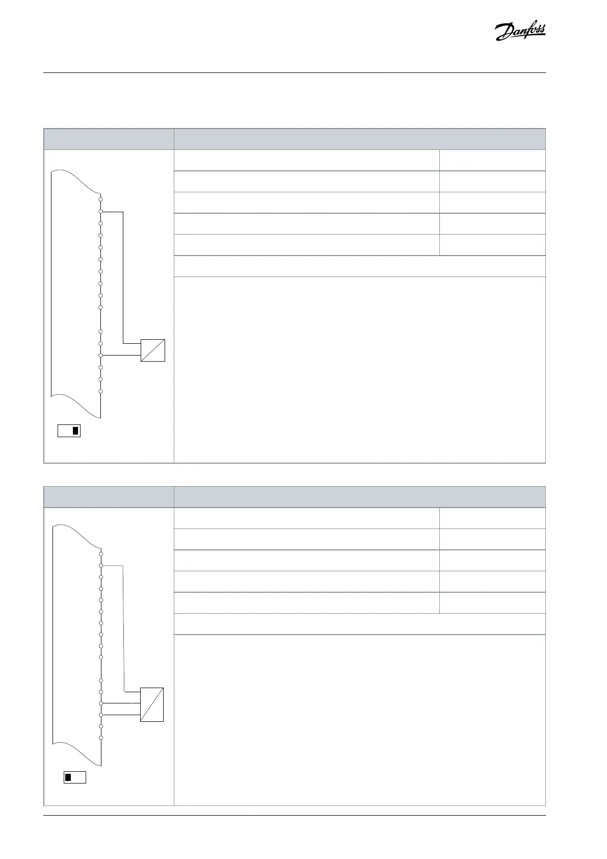
8.1.5 Wiring Configuration: Feedback
Table 80: Wiring Configuration for Analog Current Feedback Transducer (2-wire)
D IN
D IN
+10 V
A IN
A IN
COM
A OUT
COM
Parameter 6-22 Terminal 54 Low Current
Parameter 6-23 Terminal 54 High Current
Parameter 6-24 Terminal 54 Low Ref./Feedb. value
Parameter 6-25 Terminal 54 High Ref./Feedb. Value
Notes/comments:
D IN 37 is an option.
Terminal 54 in the parameter title corresponds to terminal XD2.8 in the control compartment.
Table 81: Wiring Configuration for Analog Voltage Feedback Transducer (3-wire)
+24 V
+24 V
D IN
D IN
D IN
COM
D IN
D IN
D IN
D IN
+10
Parameter 6-20 Terminal 54 Low Voltage
Parameter 6-21 Terminal 54 High Voltage
Parameter 6-24 Terminal 54 Low Ref./Feedb. value
Parameter 6-25 Terminal 54 High Ref./Feedb. Value
Notes/comments:
D IN 37 is an option.
Terminal 54 in the parameter title corresponds to terminal XD2.8 in the control compartment.
AQ262139143212en-000301 / 130R0879126 | Danfoss A/S © 2021.10
Wiring Configuration Examples
VLT® AutomationDrive FC 302
Operating Guide

 Loading...


