Line reactor overtemperature trip [°C (°F)]
dU/dt filter overtemperature trip [°C (°F)]
Sine-wave filter overtemperature trip [°C (°F)]
1
Typical power loss is at normal conditions and expected to be within ±15% (tolerance relates to variety in voltage and cable conditions.) These
values are based on a typical motor efficiency (IE/IE3 border line). Lower efficiency motors add to the power loss in the drive. Applies to dimension-
ing of drive cooling. If the switching frequency is higher than the default setting, the power losses can increase. LCP and typical control card power
consumptions are included. For power loss data according to EN 50598-2, refer to drives.danfoss.com/knowledge-center/energy-efficiency-direc-
tive/#/. Options and customer load can add up to 30 W to the losses, though usually a fully loaded control card and options for slots A and B each
add only 4 W.
2
Measured using 5 m (16.4 ft) shielded motor cables at rated load and rated frequency. Efficiency measured at nominal current. For energy efficien-
cy class, see the Ambient Conditions section. For part load losses, see drives.danfoss.com/knowledge-center/energy-efficiency-directive/#/.
3
See also Input Power Option Losses section.
4
If using an output filter, the output frequency is limited further. See
10.3.1 Motor Output (U, V, W).
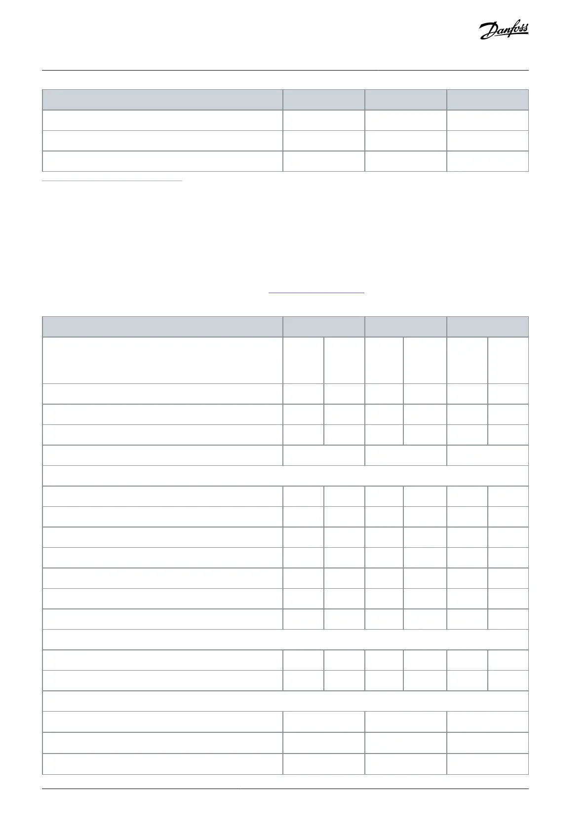
Table 108: Electrical Data, Mains Supply 3x525–690 V AC
High/normal overload
High overload=150% or 160% torque for a duration of 60 s.
Normal overload=110% torque for a duration of 60 s.
Typical shaft output at 550 V [kW]
Typical shaft output at 575 V [hp]
Typical shaft output at 690 V [kW]
Continuous (at 550 V) [A]
Intermittent (60 s overload) (at 550 V) [A]
Continuous (at 575/690 V) [A]
Intermittent (60 s overload) (at 575/690 V) [A]
Continuous kVA (at 550 V) [kVA]
Continuous kVA (at 575 V) [kVA]
Continuous kVA (at 690 V) [kVA]
Continuous (at 550 V) [A]
Continuous (at 575/690 V) [A]
Maximum number and size of cables per phase
- Mains with disconnect [mm
2
(AWG)]
- Mains with fusible disconnect [mm
2
(AWG)]
AQ262139143212en-000301 / 130R0879170 | Danfoss A/S © 2021.10
Specifications
VLT® AutomationDrive FC 302
Operating Guide

 Loading...


