The tapered tension setpoint is the tension setpoint modified based on the roll diameter and the taper setpoint. Taper
generally reduces the tension setpoint hyperbolically with a change in diameter. The PID amplifier output decreases as the
diameter increases, because the same change in reference will have a larger surface speed change as the roll increases in
diameter. Ideally, the open-loop reference signal is scaled at core so that the surface speed of the core matches line speed.
The diameter value is calculated based on the equation below.
An encoder on the feed-roll or lead-roll motor provides the line speed. An encoder on the winder motor provides the motor
speed. The winder speed is the current motor speed multiplies the gear ratio.
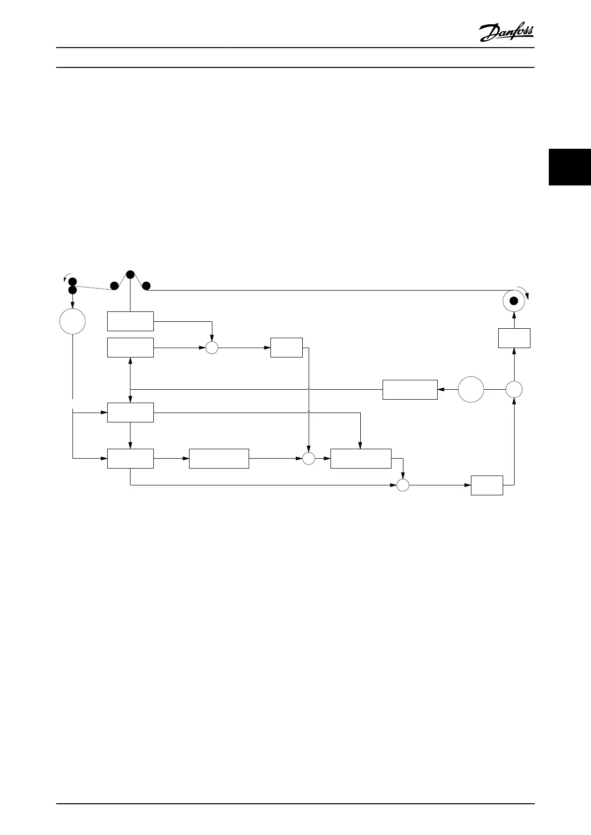
Illustration 3.2 shows the control diagram for center winder applications with FC 360 frequency converters. The amplitude of
accommodation depends on the change of diameter and the difference between tension feedback and tension setpoint.
PID
V
Web speed at the
winder roll [m/sec]
V1
Web speed at the
lead roll [m/sec]
Load cell or
dancer
Encoder
Encoder
TensionFBHdl
TensionRefHdl
DiameterHdl
Feed Forward
Calculation
Feed Forward Accel Tension Loop Prole
Speed FB Handler M
Gear Ratio
Tension err
Tension
set point
Tension Feedback
Diameter
Diameter
Diameter
Winder speed
Line Speed
Speed Set Point
+
+
+
+
+
+
_
MOC
130BD801.10
Illustration 3.2 Center Winder Control with FC 360
The frequency converter adjusts the operation of the winder based on the states of a roll, such as ready-to-run, end-of-roll,
running-on-tension-loop and tension-over-limit. For example, a frequency converter can stop winding for a roll change.
The frequency converter can be controlled through either digital inputs or PROFIBUS.
3.1.1
Features
The following features are provided to increase the overall
stability of the winder, and improve the control and
monitoring of the winding process.
•
Acceleration feed-forward: This function allows a
shift in the tension/taper setpoint based on
changes in line speed. It provides a tension boost
during initial acceleration to help compensate for
system inertia.
•
Tension-taper setpoint ramp: The tapered tension
setpoint generator integrates any changes to the
tension or taper setpoints over multiple program
scans. A parameter is provided to increase or
decrease response time.
•
Diameter calculator minimum speed: There is also
a minimum speed requirement to enable the
diameter calculator. At low speeds, the line and
winder speeds may not have enough resolution
to accurately calculate diameter. A parameter is
provided to define a minimum line speed
required for the diameter calculator to function.
Until that speed is reached, the diameter value
will not change.
Center Winder Control Application Guide
MG06E102 Danfoss A/S © 11/2014 All rights reserved. 7
3 3

 Loading...


