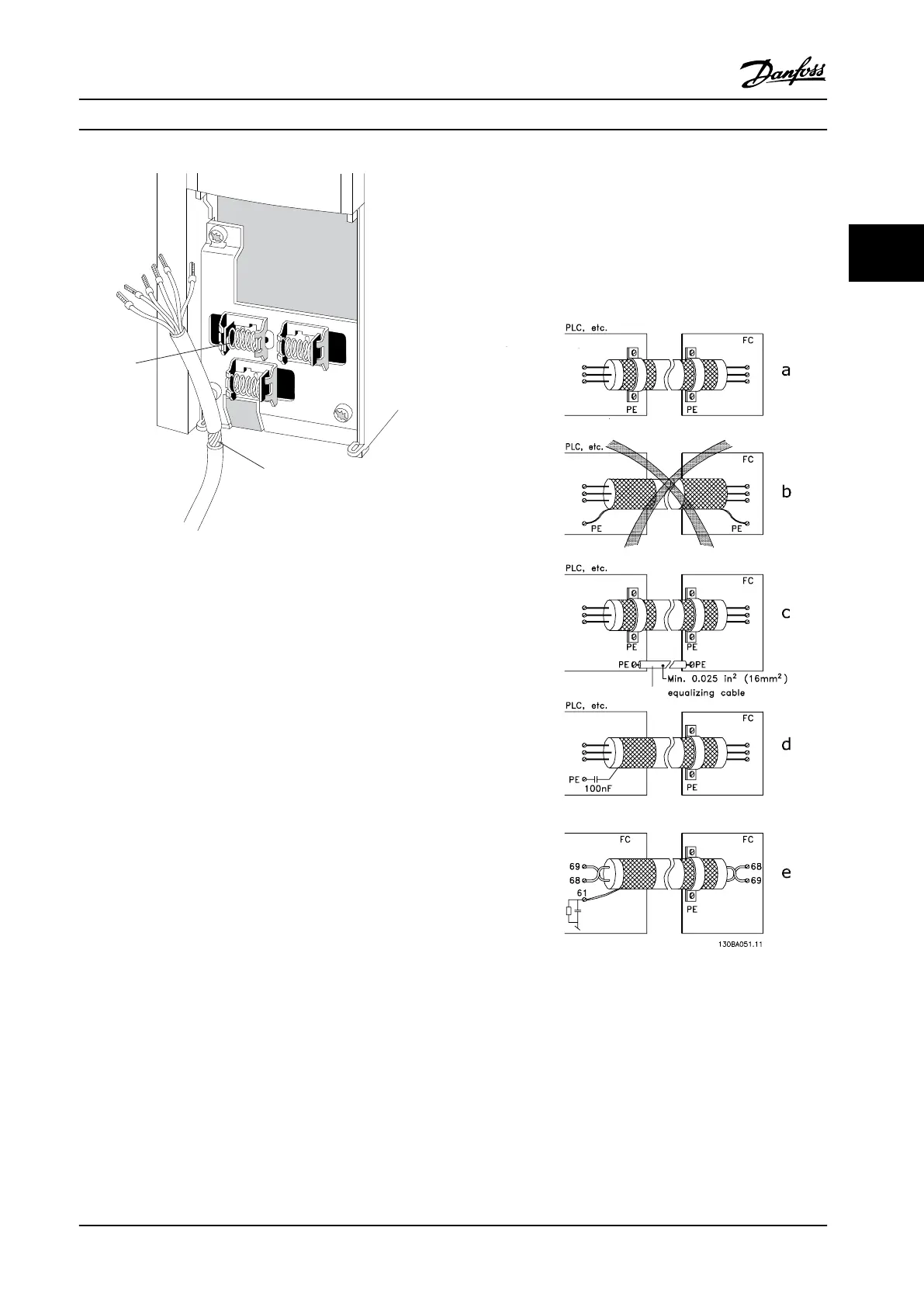
Figure 3.25 Control Cable Connection
Figure 3.26 indicates how correct grounding is carried out
and what to do if in doubt.
a. Correct grounding
Control cables and cables for serial communication must
be
tted with cable clamps at both ends to ensure the
best possible electrical contact.
b. Wrong grounding
Do not use twisted cable ends (pigtails). They increase the
screen impedance at high frequencies.
c. Protection concerning ground potential between PLC
(Program Logic Controller) and frequency converter
If the ground potential between the frequency converter
and the PLC (etc.) is dierent, electric noise may occur that
disturbs the entire system. Solve this problem by tting an
equalizing cable, next to the control cable. Minimum cable
cross-section: 16 mm
2
.
d. For 50/60 Hz ground loops
If long control cables are used, 50/60 Hz ground loops may
occur. Solve this problem by connecting one end of the
screen to ground via a 100 nF capacitor (keeping leads
short).
e. Cables for serial communication
Eliminate low-frequency noise currents between two
frequency converters by connecting one end of the screen
to terminal 61. This terminal is connected to ground via an
internal RC link. To reduce the dierential mode
interference between the conductors, use twisted-pair
cables.
Figure 3.26 Examples of ground Wiring
How to Install Operating Instructions
MG34M422 Danfoss A/S © Rev. 2013-07-03 All rights reserved. 25
3 3