1
Circuit breakers have not been evaluated by Danfoss as part of the certification process.
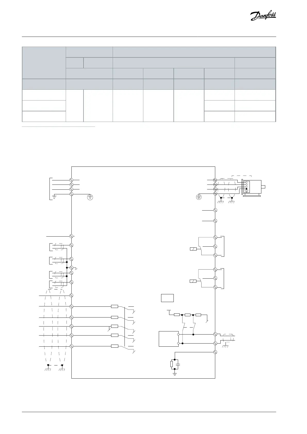
6.3 Electrical Wiring
6.3.1 Wiring Schematic
+10 V DC
0-10 V DC-
0-10 V DC-
50 (+10 V OUT)
54 (A IN)
53 (A IN)
55 (COM A IN/OUT)
42 0/4-20 mA A OUT / D OUT
45 0/4-20 mA A OUT / D OUT
18 (D IN)
19 (D IN)
27 (D IN)
29 (
12 (+24 V OUT)
24 V (NPN)
20 (COM D IN)
O V (PNP)
24 V (NPN)
O V (PNP)
24 V (NPN)
O V (PNP)
24 V (NPN)
O V (PNP)
Bus ter.
Bus ter.
RS485
Interface
RS485
(N RS485) 69
(P RS485) 68
(Com RS485 ) 61
(PNP)-Source
(NPN)-Sink
ON=Terminated
OFF=Unterminated
ON
1 2
240 V AC 3 A
Not present on all power sizes
Do not connect shield to 61
01
02
03
relay 1
relay 2
UDC+
UDC-
Motor
U
V
W
e30bj246.10
06
05
04
240 V AC 3 A
Illustration 27: Basic Wiring Schematic Drawing
AJ330233902305en-000201 / 130R059646 | Danfoss A/S © 2021.05
Electrical Installation
Considerations
VLT® Compressor Drive CDS 803
Design Guide