8.1.3. Drive Will Not Respond to Control Signals
- Danfoss Control Word profile (instances 100/150 and 101/151)
Check 1: Is the Control word valid?
If bit 10=0 in the Control word, then the frequency converter will not accept the Control word,
because the default setting is bit 10=1. Set bit 10=1 via the PLC.
Check 2: Is the relationship between bits in the Control word and the terminal I/Os correct?
Check the logical relationship in the frequency converter.
Set the logic to bit 3=1 AND digital input=1 in order to achieve a successful start.
Define the desired logical relationship in par. 8-50 to 8-56 according to the following range of
options. Select the FC control mode, digital input and/or bus communication, using par. 8-50 to
8-56.
The tables below show the effect upon the frequency converter of a coast command for the full
range of par. 8-50 settings.
The effect of control mode upon the function of par. 8-50
Coasting Select
, 8-51
Quick Stop Se-
lect
and 8-52
DC Brake Select
is as follows:
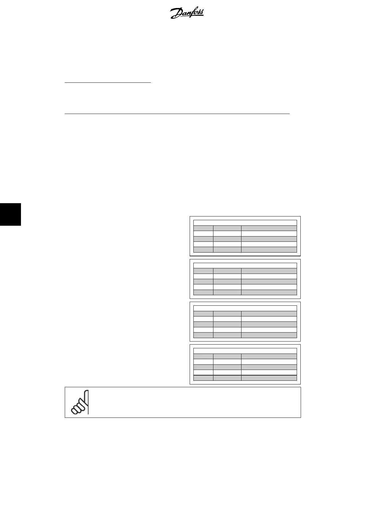
If
Digital input
[0] is selected, the terminals
will control the Coast and DC Brake functions.
Par. 8-50/51/52 setting:
Digital Input [0]
Terminal Bit 02/03/04 Function
0 0 Coast/DC brake/Q-Stop
0 1 Coast/DC brake/Q-Stop
1 0 No Coast/DC brake/Q-Stop
1 1 No Coast/DC brake/Q-Stop
If Bus [1] is selected, commands will be acti-
vated only when given via the control word.
Par. 8-50/51/52 setting:
Bus [1]
Terminal Bit 02/03/04 Function
0 0 Coast/DC brake/Q-Stop
0 1 No Coast/DC brake/Q-Stop
1 0 Coast/DC brake/Q-Stop
1 1 No Coast/DC brake/Q-Stop
If Logic AND [2] is selected, both signals must
be activated to perform the function.
Par. 8-50/51/52 setting:
Logic AND [2]
Terminal Bit 02/03/04 Function
0 0 Coast/DC brake/Q-Stop
0 1 No Coast/DC brake/Q-Stop
1 0 No Coast/DC brake/Q-Stop
1 1 No Coast/DC brake/Q-Stop
If Logic OR [3] is selected, activation of one
signal will activate the function.
Par. 8-50/51/52 setting:
Logic OR [3]
Terminal Bit 02/03/04 Function
0 0 Coast/DC brake/Q-Stop
0 1 Coast/DC brake/Q-Stop
1 0 Coast/DC brake/Q-Stop
1 1 No Coast/DC brake/Q-Stop
NB!
Please note that Coasting, Quick Stop and DC brake functions are active for logic
“0’’.
8. Troubleshooting FC 100/ 200/ 300 DeviceNet
76
MG.33.D3.02 - VLT
®
is a registered Danfoss trademark
8
 Loading...


