Leave the screen as close to the connectors as possible.
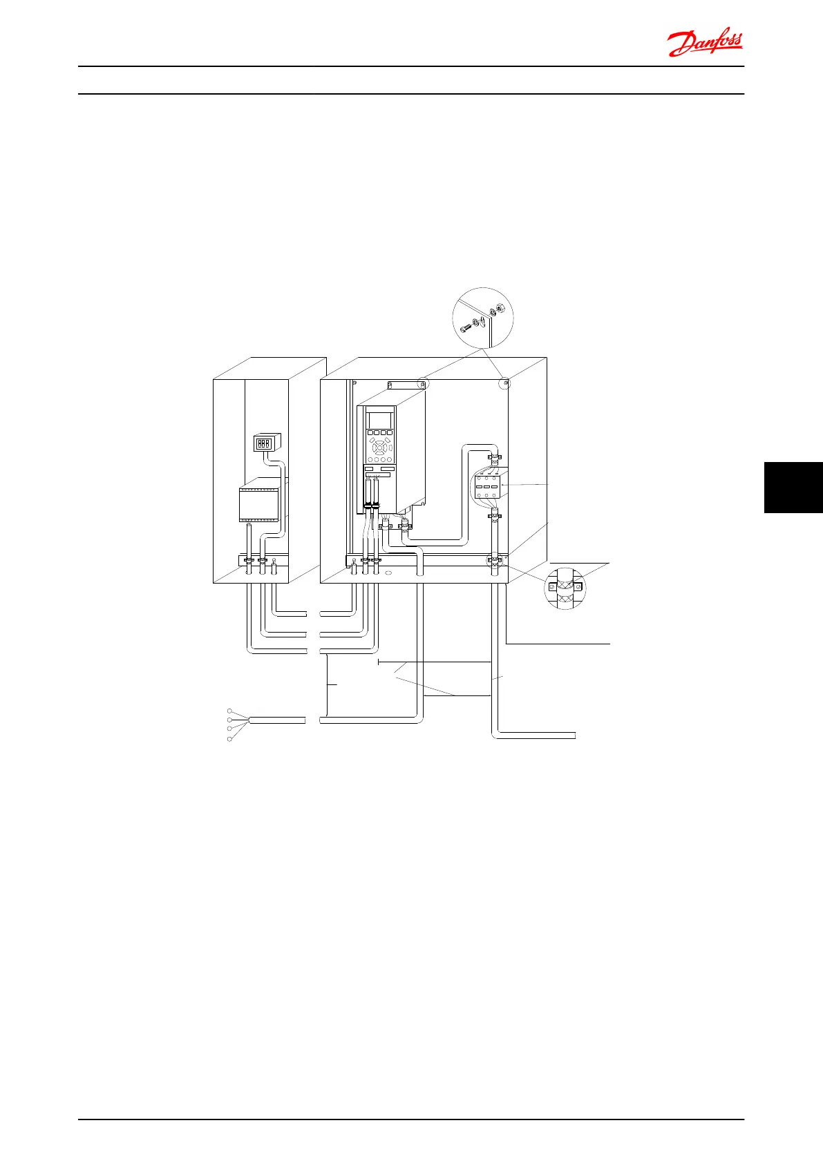
Illustration 8.63 shows an example of an EMC-correct
electrical installation of an IP 20 frequency converter. The
frequency converter is fitted in an installation cabinet with
an output contactor and connected to a PLC, which is
installed in a separate cabinet. Other ways of doing the
installation may have just as good an EMC performance,
provided the above guide lines to engineering practice are
followed.
If the installation is not carried out according to the
guideline and if unscreened cables and control wires are
used, some emission requirements are not complied with,
although the immunity requirements are fulfilled. See the
paragraph EMC test results.
130BA048.13
L1
L2
L3
PE
Min. 16 mm
2
Equalizing cable
Control cables
All cable entries in
one side of panel
Earthing rail
Cable insula-
tion stripped
Output con-
tactor etc.
Min. 200mm
between con-
trol cables,
motor cable and
Motor cable
Motor, 3 phases and
PLC etc.
Panel
Mains-supply
mains cable
PLC
Protective earth
Reinforced protective earth
Illustration 8.63 EMC-correct Electrical Installation of a Frequency Converter in Cabinet.
Electrical Installation FC 300 Design Guide
MG.33.BD.02 - VLT
®
is a registered Danfoss trademark 221
8 8
 Loading...


