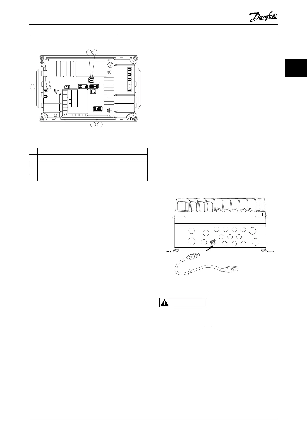
Illustration 2.19 Location of DIP Switches
1 S201 - terminal 53
2 S202 - terminal 54
3 S801 - standard bus termination
4 Profibus termination
5 Fieldbus address
NOTE
Switches 4 and 5
are only valid for units fitted with
fieldbus options.
2.4.14 Serial Communication
Connect RS-485 serial communication wiring to terminals
(+)68 and (-)69.
•
Switch S801
(BUS TER.) can be used to enable
termination on the RS-485 port (terminals 68 and
69). See Illustration 2.19.
•
Shielded serial communication cable is
recommended
•
See 2.4.11 Earth (Grounding) Requirements for
proper grounding
•
Two communication protocols are internal to the
frequency converter
•
Danfoss FC
•
Modbus RTU
•
For basic serial communication setup, select the
following
•
Protocol type in 8-30 Protocol
•
Frequency converter address in
8-31 Address
•
Baud rate in 8-32 FC Port Baud Rate
•
Functions can be programmed remotely using
the protocol software and RS-485 connection or
in parameter group 8-** Communications and
Options
•
Selecting
a specific communication
protocol
changes various default parameter settings to
match that specifications of the protocol along
with making additional protocol-specific
parameters available
•
Control card options are available to provide
additional communication protocols. See the
option-card documentation for installation and
operation instructions
•
Profibus
•
Ethernet IP
•
ProfiNet
2.4.15 Connection to PC
To control the frequency converter from a PC, install the
MCT
10 Set-up Software.
The
PC is connected via a standard (host/device) USB
cable, or via the RS-485 interface.
Illustration 2.20 Electronic Part
CAUTION
The USB connection is galvanically isolated from the
supply voltage (PELV) and
other high-voltage terminals.
The USB connection is
not galvanically isolated from
protection earth. Use only
isolated laptop/PC as connection
to the USB connector on frequency converter or an
isolated USB cable/converter.
2.4.16 Safe Stop
The FCD 302 provides safe stop functionality via control
terminal
37.
Safe
stop
disables the control voltage of the
power semiconductors of the frequency controller output
stage. This in turn prevents generating the voltage
required to rotate the motor. When the Safe Stop (T37) is
Installation
VLT
®
Decentral Drive FCD 302 Operating Instructions
MG04F302 - VLT
®
is a registered Danfoss trademark
25
2 2
Phone: 800.894.0412 - Fax: 888.723.4773 - Web: www.clrwtr.com - Email: info@clrwtr.com

 Loading...


