If 8-04 Control Word Timeout Function is set to [Stop] and
[Trip], a warning appears and the frequency converter
ramps down until it trips, while giving an alarm.
8-03 Control Word Timeout Time could possibly be
increased.
WARNING/ALARM 22, Hoist Mechanical Brake:
The report value shows what kind it is. 0=The torque ref.
was not reached before timeout. 1=There was no brake
feedback before timeout.
WARNING 23, Internal fan fault:
The fan warning function is an extra protection function
that checks if the fan is running/mounted. The fan warning
can be disabled in 14-53 Fan Monitor (set to [0] Disabled).
WARNING 25, Brake resistor short-circuited:
The brake resistor is monitored during operation. If it
short-circuits, the brake function is disconnected and the
warning appears. The frequency converter still works, but
without the brake function. Turn off the frequency
converter and replace the brake resistor (see 2-15 Brake
Check).
WARNING/ALARM 26, Brake resistor power limit:
The power transmitted to the brake resistor is calculated as
a percentage, as a mean value over the last 120 s, based
on the resistance value of the brake resistor (2-11 Brake
Resistor (ohm)) and the intermediate circuit voltage. The
warning is active when the dissipated braking power is
higher than 90%. If [2] Trip has been selected in 2-13 Brake
Power Monitoring, the frequency converter cuts out and
issues this alarm, when the dissipated braking power is
higher than 100%.
WARNING/ALARM 27, Brake chopper fault:
The brake transistor is monitored during operation and if it
short-circuits, the brake function disconnects and the
warning comes up. The frequency converter is still able to
run. However because the brake transistor has short-
circuited, substantial power is transmitted to the brake
resistor, even when it is inactive.
Turn off the frequency converter and remove the brake
resistor.
This alarm/ warning can also arise due to overheating of
the brake resistor. Terminals 104 to 106 are available as
brake resistor, with Klixon inputs.
CAUTION
There is a risk of substantial power being transmitted to
the
brake
resistor
if
the brake transistor is short-circuited.
WARNING/ALARM 28, Brake check failed:
Brake resistor fault: the
brake resistor is not connected/
working.
ALARM 29, Drive over temperature:
The cut-out temperature of the heat-sink is 95
º
C
+5
º
C. The
temperature fault cannot
be reset, until the temperature of
the heatsink is below 70
º
C +/- 5
º
C.
The fault could be:
- Ambient
temperature too high
- Too
long motor cable
ALARM 30, Motor phase U missing:
Motor phase U between the frequency converter and the
motor is missing.
Turn off the frequency converter and check motor phase
U.
ALARM 31, Motor phase V missing:
Motor phase V between the frequency converter and the
motor is missing.
Turn off the frequency converter and check motor phase V.
ALARM 32, Motor phase W missing:
Motor phase W between the frequency converter and the
motor is missing.
Turn off the frequency converter and check motor phase
W.
ALARM 33, Inrush fault:
Too many power ups have occurred within a short time
period. See 8.2 General Specifications for the allowed
number of power ups within 1 minute.
WARNING/ALARM 34, Fieldbus communication fault:
The fieldbus on the communication option card is not
working correctly. Check parameters associated with the
module and check the wiring for fieldbus.
WARNING/ALARM 36, Mains failure:
This warning/alarm is only active if the supply voltage to
the frequency converter is lost and 14-10 Mains Failure is
NOT set to [Off]. Possible correction: check the fuses to the
frequency converter
ALARM 37, Phase imbalance:
There is a current imbalance between the power units
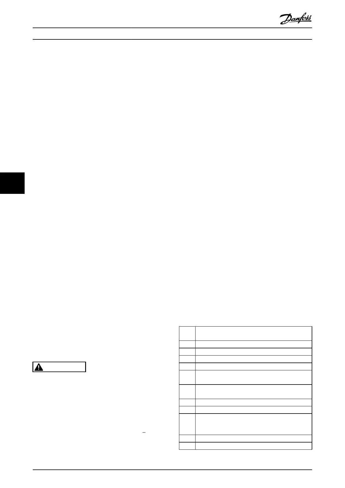
ALARM 38, Internal fault:
When this alarm arises, it can be necessary to contact the
Danfoss supplier. Some typical alarm messages:
0 The serial port cannot be initialized. Serious hardware
failure
256 The power EEPROM data is defect or too old
512 The control board EEPROM data is defect or too old
513 Communication time out Reading EEPROM data
514 Communication time out Reading EEPROM data
515 The Application Orientated Control cannot recognize the
EEPROM
data
516 Cannot write
to the EEPROM because a write command
is on progress
517 The
write command is under time-out
518 Failure in the EEPROM
519 Missing or invalid BarCode data in EEPROM 1024-1279
CAN
telegram cannot be sent. (1027 indicate a possible
hardware failure)
1281 Digital Signal Processor flash time-out
1282 Power micro software version mismatch
Troubleshooting
VLT
®
Decentral Drive FCD 302 Operating Instructions
72 MG04F302 - VLT
®
is a registered Danfoss trademark
77
Phone: 800.894.0412 - Fax: 888.723.4773 - Web: www.clrwtr.com - Email: info@clrwtr.com

 Loading...


