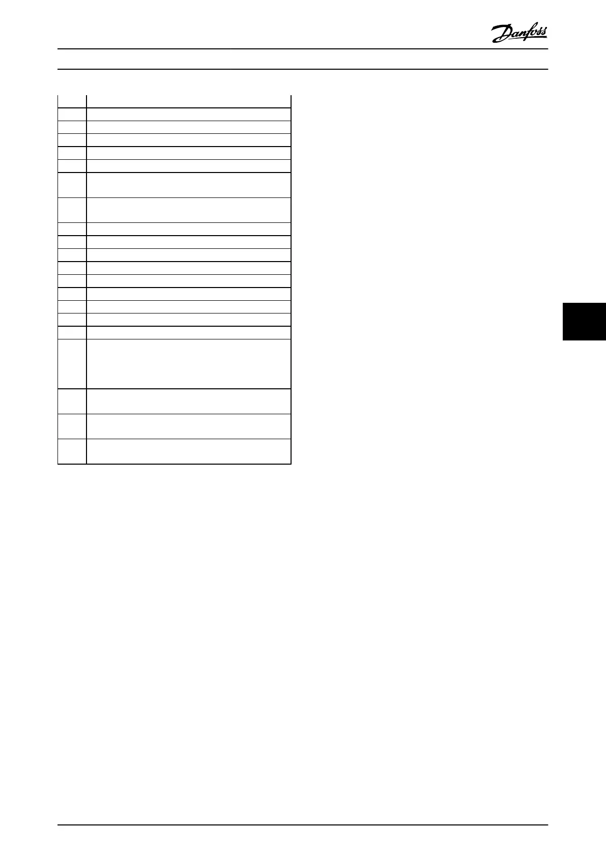
1283 Power EEPROM data version mismatch
1284 Cannot read Digital Signal Processor software version
1299 Option SW in slot A is too old
1300 Option SW in slot B is too old
1315 Option SW in slot A is not supported (not allowed)
1316 Option SW in slot B is not supported (not allowed)
1536 An exception in the Application Orientated Control is
registered.
Debug
information
written
in LCP
1792 DSP watchdog is active. Debugging of power part data
Motor Orientated Control data
not transferred correctly
2049 Power data restarted
2315 Missing SW version from power unit
2816 Stack overflow Control board module
2817 Scheduler slow tasks
2818 Fast tasks
2819 Parameter thread
2820 LCP stack overflow
2821 Serial port overflow
2822 USB port overflow
3072-
5122
Parameter value is outside its limits. Perform an initiali-
zation.
Parameter number causing
the alarm: Subtract
the code from 3072. Ex Error code 3238: 3238-3072=166
is outside the limit
5123 Option in slot A: Hardware incompatible with Control
board hardware
5124 Option in
slot B: Hardware incompatible with Control
board hardware
5376-
6231
Out of memory
ALARM 39, Heatsink sensor
No feedback from the
heatsink temperature sensor.
The signal from the IGBT thermal sensor is not available on
the power card. The problem could be on the power card,
on the gate drive card, or the ribbon cable between the
power card and gate drive card.
WARNING 40, Overload of Digital Output Terminal 27
Check the load connected to terminal 27 or remove short-
circuit connection. Check 5-00 Digital I/O Mode and
5-01 Terminal 27 Mode.
WARNING 41, Overload of Digital Output Terminal 29:
Check the load connected to terminal 29 or remove short-
circuit connection. Check 5-00 Digital I/O Mode and
5-02 Terminal 29 Mode.
ALARM 45, Earth fault 2:
There is a discharge from the output phases to earth,
either in the cable between the frequency converter and
the motor or in the motor itself. Turn off the frequency
converter and remove the earth fault. This alarm is
detected under the start-up test sequence.
ALARM 46, Power card supply
The supply on the power card is out of range.
There are three power supplies generated by the switch
mode power supply (SMPS) on the power card: 24 V, 5 V,
+/-18 V. When powered with 24 V DC with the MCB 107
option,
only the 24
V and 5 V supplies are monitored.
When powered with three-phase mains voltage, all three
phases supplied are monitored.
WARNING 47, 24 V supply low:
The external 24 V DC backup power supply may be
overloaded, otherwise Contact your Danfoss supplier.
WARNING 48, 1.8 V supply low:
Contact your Danfoss supplier.
WARNING 49, Speed limit:
The speed is not within the specified range in 4-11 Motor
Speed Low Limit [RPM] and 4-13 Motor Speed High Limit
[RPM].
ALARM 50, AMA calibration failed:
The motor is not suitable for the particular size of drive.
Start the AMA procedure once again by 1-29 Automatic
Motor Adaptation (AMA), eventually with a reduced AMA
function. If still failing; check the motor data.
ALARM 51, AMA check Unom and Inom:
The setting of motor voltage, motor current, and motor
power is presumably wrong. Check the settings.
ALARM 52, AMA low Inom:
The motor current is too low. Check the settings.
ALARM 53, AMA motor too big:
The motor is too large for the AMA to be carried out.
ALARM 54, AMA motor too small:
The motor is too small for the AMA to be carried out.
ALARM 55, AMA par. out of range:
The motor parameter values found from the motor are
outside acceptable range.
ALARM 56, AMA interrupted by user:
The AMA has been interrupted by the user.
ALARM 57, AMA timeout:
Try to start the AMA again a number of times, until the
AMA is carried out. Note that repeated runs may heat the
motor to a level where the resistance R
s
and R
r
are
increased. In most cases, however, this is not critical.
ALARM 58, AMA internal fault:
Contact your Danfoss supplier.
WARNING 59, Current limit:
The current is higher than the value in 4-18 Current Limit.
WARNING 60, External interlock
External interlock has been activated. To resume normal
operation, apply 24 V DC to the terminal programmed for
external interlock and reset the frequency converter (via
serial communication, digital I/O, or by pressing [Reset]).
WARNING/ALARM 61, Feedback Error:
An error between calculated speed and speed
measurement from feedback device. The function Warning/
Alarm/Disabling setting is in 4-30 Motor Feedback Loss
Function. Accepted error setting in 4-31 Motor Feedback
Speed Error and the allowed time the error occur setting in
Troubleshooting
VLT
®
Decentral Drive FCD 302 Operating Instructions
MG04F302 - VLT
®
is a registered Danfoss trademark
73
7 7
Phone: 800.894.0412 - Fax: 888.723.4773 - Web: www.clrwtr.com - Email: info@clrwtr.com

 Loading...


