Digital inputs
Programmable digital inputs 4 (6)
1)
Terminal number 18, 19, 27
1)
, 29
1)
, 32, 33,
Logic PNP or NPN
Voltage level 0-24 V DC
Voltage level, logic'0' PNP <5 V DC
Voltage level, logic'1' PNP >10 V DC
Voltage level, logic '0' NPN
2)
> 19 V DC
Voltage level, logic '1' NPN
2)
< 14 V DC
Maximum voltage on input 28 V DC
Pulse frequency range 0-110 kHz
(Duty cycle) Min. pulse width 4.5 ms
Input resistance, R
i
approx. 4 kΩ
All digital inputs are galvanically isolated from the supply voltage (PELV) and other high-voltage terminals.
1) Terminals 27 and
29 can also be programmed as output.
Safe stop Terminal 37 (Terminal 37 is fixed PNP logic)
Voltage level 0-24 V DC
Voltage level, logic'0' PNP <4 V DC
Voltage level, logic'1' PNP 20 V DC
Nominal input current at 24 V 50 mA rms
Nominal input current at 20 V 60 mA rms
Input capacitance 400 nF
Analog inputs
Number of analog inputs 2
Terminal number 53, 54
Modes Voltage or current
Mode select Switch S201 and switch S202
Voltage mode Switch S201/switch S202=OFF (U)
Voltage level -10 to +10 V (scaleable)
Input resistance, R
i
approx. 10 kΩ
Max. voltage ± 20 V
Current mode Switch S201/switch S202 = ON (I)
Current level 0/4 to 20 mA (scaleable)
Input resistance, R
i
approx. 200Ω
Max. current 30 mA
Resolution for analog inputs 10 bit (+ sign)
Accuracy of analog inputs Max. error 0.5% of full scale
Bandwidth 100 Hz
The analog inputs are galvanically isolated from the supply voltage (PELV) and other high-voltage terminals.
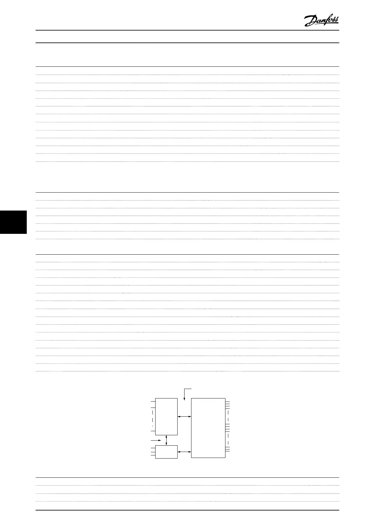
Mains
Functional
isolation
PELV isolation
Motor
DC-Bus
High
voltage
Control
+24V
RS485
18
37
130BA117.10
Pulse/encoder inputs
Programmable pulse/encoder inputs 2/1
Terminal number pulse/encoder 29, 33
1)
/ 32
2)
, 33
2)
Max. frequency at terminal 29, 32, 33 110 kHz (Push-pull driven)
Specifications
VLT
®
Decentral Drive FCD 302 Operating Instructions
78 MG04F302 - VLT
®
is a registered Danfoss trademark
88
Phone: 800.894.0412 - Fax: 888.723.4773 - Web: www.clrwtr.com - Email: info@clrwtr.com

 Loading...


