130BE214.10
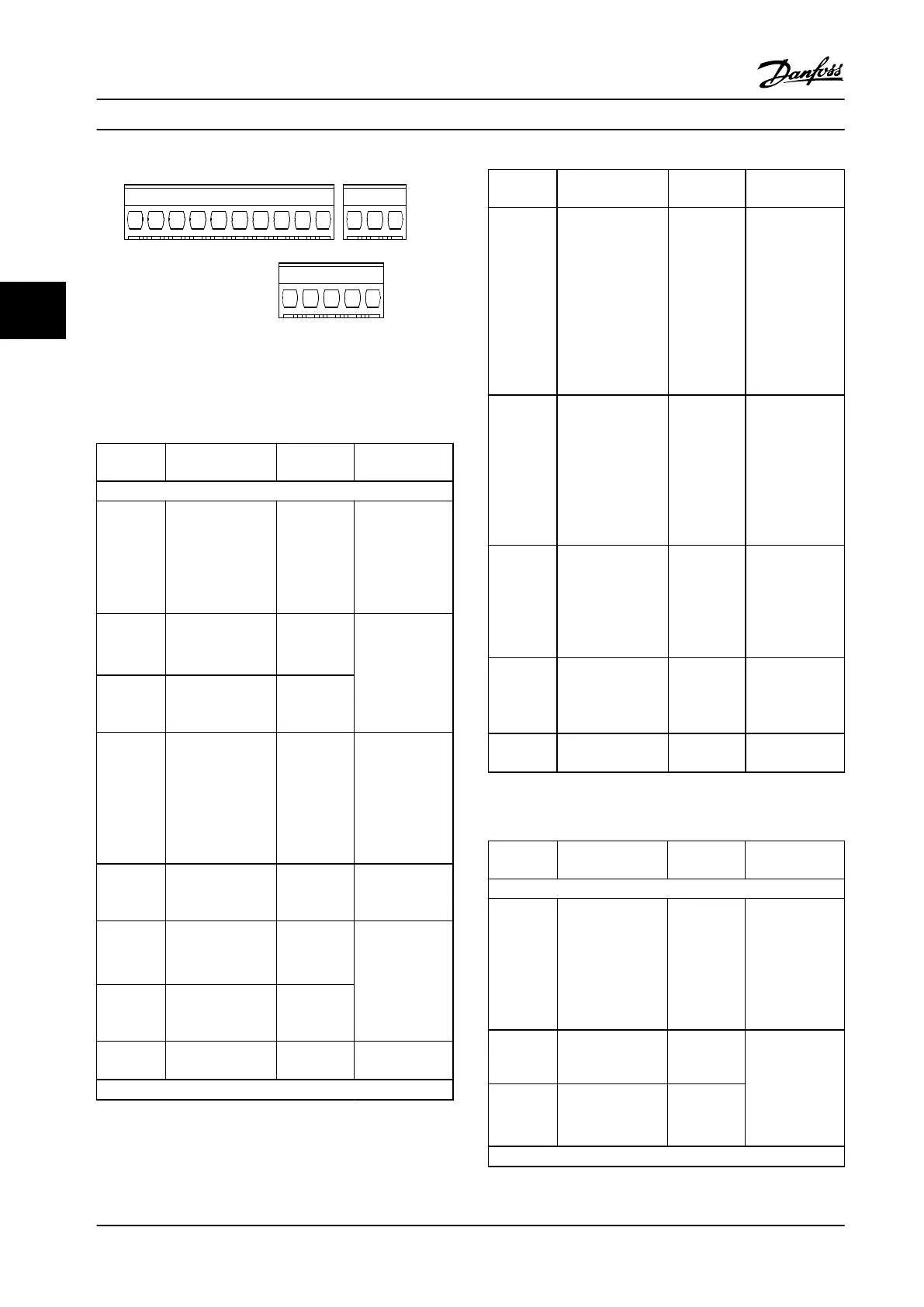
37 38 12 13 18 19 27 29 32 33 61
42 53 54 50 55
68 69
1
3
2
Figure 4.9 Terminal Numbers
See chapter 9.6 Control Input/Output and Control Data for
terminal ratings details.
Terminal Parameter
Default
setting
Description
Digital I/O, Pulse I/O, Encoder
12, 13 – +24 V DC
24 V DC supply
voltage.
Maximum
output current is
100 mA for all
24 V loads.
18
Parameter 5-10 Ter
minal 18 Digital
Input
[8] Start
Digital inputs.
19
Parameter 5-11 Ter
minal 19 Digital
Input
[10]
Reversing
27
Parameter 5-12 Ter
minal 27 Digital
Input
parameter 5-30 Ter
minal 27 Digital
Output
DI [2] Coast
inverse
DO [0] No
operation
Selectable for
either digital
input, digital
output or pulse
output. The
default setting is
digital input.
29
Parameter 5-13 Ter
minal 29 Digital
Input
[14] Jog Digital input.
32
Parameter 5-14 Ter
minal 32 Digital
Input
[0] No
operation
Digital input, 24
V encoder.
Terminal 33 can
be used for
pulse input.
33
Parameter 5-15 Ter
minal 33 Digital
Input
[16] Preset ref
bit 0
37, 38 -
STO Functional safety
inputs.
Analog inputs/outputs
Terminal Parameter
Default
setting
Description
42
Parameter 6-91 Ter
minal 42 Analog
Output
[0] No
operation
Programmable
analog output.
The analog
signal is 0–20
mA or 4–20 mA
at a maximum
of 500 Ω. Can
also be
congured as
digital outputs.
50 – +10 V DC
10 V DC analog
supply voltage.
15 mA
maximum
commonly used
for potenti-
ometer or
thermistor.
53
6-1* parameter
group
–
Analog input.
Only voltage
mode is
supported. It can
also be used as
digital input.
54
6-2* parameter
group
–
Analog input.
Selectable
between voltage
or current mode.
55 –
–
Common for
analog input.
Table 4.1 Terminal Descriptions - Digital Inputs/Outpus,
Analog Input/Outputs
Terminal Parameter
Default
setting
Description
Serial communication
61 – –
Integrated RC
lter for cable
shield. ONLY for
connecting the
shield when
experiencing
EMC problems.
68 (+)
8-3* parameter
group
–
RS485 interface.
A control card
switch is
provided for
termination
resistance.
69 (-)
8-3* parameter
group
–
Relays
Electrical Installation
VLT
®
Midi Drive FC 280
16 Danfoss A/S © 11/2015 All rights reserved. MG07A122
44
 Loading...


