7 Application Examples
The examples in this section are intended as a quick
reference for common applications.
•
Parameter settings are the regional default values
unless otherwise indicated (selected in
parameter 0-03 Regional Settings).
•
Parameters associated with the terminals and
their settings are shown next to the drawings.
•
Required switch settings for analog terminals 53
or 54 are also shown.
NOTICE!
When the STO feature is not used, a jumper wire is
required between terminals 12, 37 and 38 for the
adjustable frequency drive to operate with factory
default programming values.
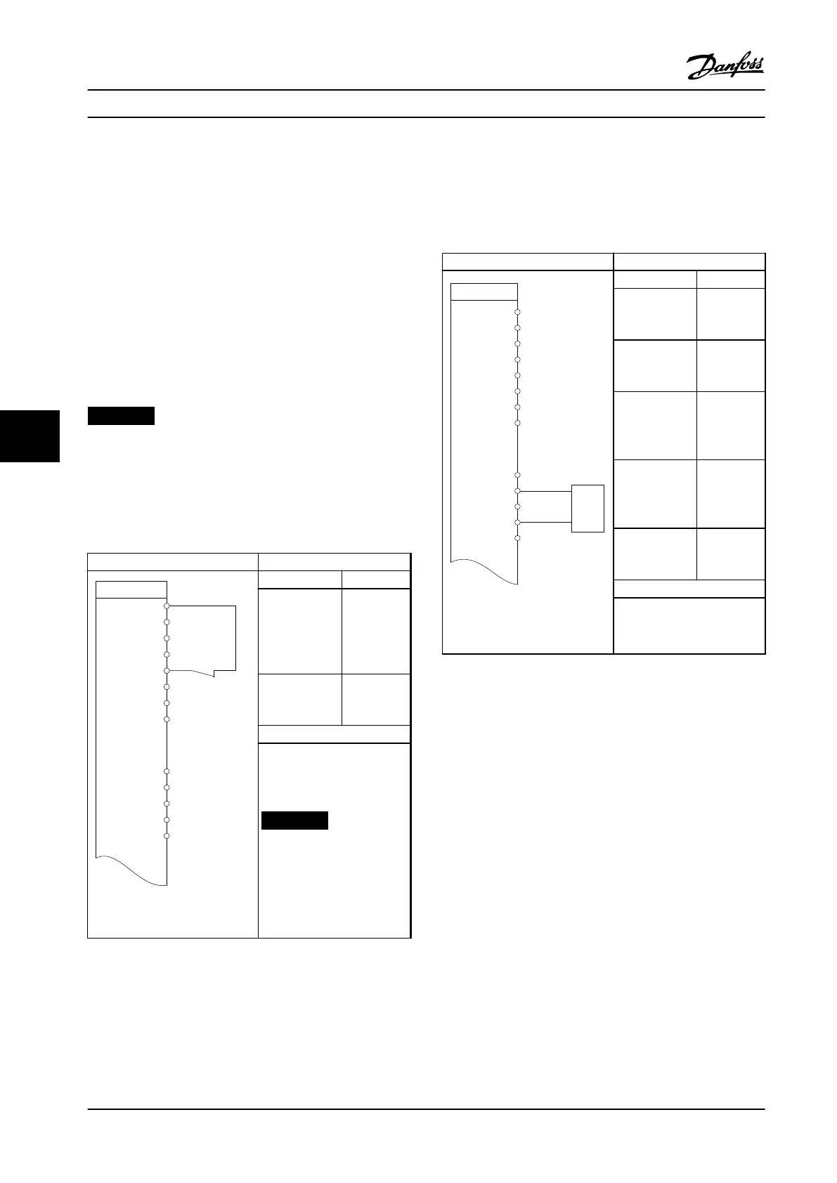
7.1.1 AMA
Parameters
130BE203.11
FC
+24 V
D IN
D IN
D IN
D IN
D IN
+10 V
A IN
A IN
COM
12
13
18
19
27
29
32
33
50
53
54
55
42
A OUT
D IN
+24 V
Function Setting
Parameter 1-29
Automatic
Motor
Adaptation
(AMA)
[1] Enable
complete
AMA
Parameter 5-12
Terminal 27
Digital Input
*[2] Coast
inverse
*=Default value
Notes/comments: Set
parameter group 1-2* Motor
Data according to motor
specications.
NOTICE!
If terminal 12 and 27 are
not connected, set
parameter 5-12 Terminal
27 Digital Input to [0] No
operation.
Table 7.1 AMA with T27 Connected
7.1.2 Speed
Parameters
130BE204.11
+24 V
D IN
D IN
D IN
D IN
D IN
D IN
+10 V
A IN
A IN
COM
A OUT
12
13
18
19
27
29
32
33
50
53
54
55
42
0 ~10 V
+
-
FC
+24 V
Function Setting
Parameter 6-10
Terminal 53 Low
Voltage
0.07 V*
Parameter 6-11
Terminal 53
High Voltage
10 V*
Parameter 6-14
Terminal 53 Low
Ref./Feedb.
Value
0
Parameter 6-15
Terminal 53
High Ref./Feedb.
Value
50
Parameter 6-19
Terminal 53
mode
[1] Voltage
*=Default value
Notes/comments:
Table 7.2 Analog Speed Reference (Voltage)
Application Examples
VLT
®
Midi Drive FC 280
38 Danfoss A/S © 11/2015 All rights reserved. MG07A122
77

 Loading...


