6 Safe Torque O (STO)
The Safe Torque O (STO) function is a component in a
safety control system. STO prevents the unit from
generating the energy that is required to rotate the motor,
thus ensuring safety in emergency situations.
The STO function is designed and approved suitable for
the requirements of:
•
IEC/EN 61508: 2010 SIL 2
•
IEC/EN 61800-5-2: 2007 SIL2
•
IEC/EN 62061: 2012 SILCL of SIL2
•
EN ISO 13849-1: 2008 Category 3 PL d
To achieve the desired level of operational safety, select
and apply the components in the safety control system
appropriately. Before using STO, carry out a thorough risk
analysis on the installation to determine whether the STO
function and safety levels are appropriate and sucient.
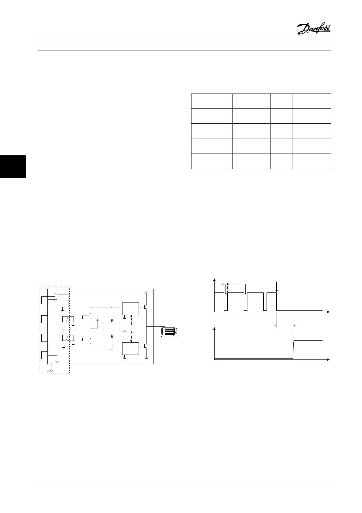
The STO function in the adjustable frequency drive is
controlled via control terminals 37 and 38. When STO is
activated, the power supply on the high side and low side
of the IGBT gate driving circuits are cut o. Figure 6.1
shows the STO architecture. Table 6.1 shows STO statuses
based on whether terminals 37 and 38 are energized.
24 V
17 V
IGBT
+UDC
X3
IGBT
PELV
X3
X3
24 V
voltage
source
high-side
gate driving
circuit
diagnostic
circuit
low-side
gate driving
circuit
12
38
37
55
130BE463.11
Figure 6.1 STO Architecture
Terminal 37 Terminal 38 Torque Warning or
alarm
Energized
1)
Energized
Yes
2)
No warnings or
alarms.
De-energized
3)
De-energized No Warning/alarm
68: Safe Stop.
De-energized Energized No Alarm 188: STO
Function Fault.
Energized De-energized No Alarm 188: STO
Function Fault.
Table 6.1 STO Status
1) Voltage range is 24 V
±
5 V, with terminal 55 as the reference
terminal.
2) Torque is present only when the adjustable frequency drive is
operating.
3) Open circuit, or the voltage within the range of 0 V
±
1.5 V, with
terminal 55 as the reference terminal.
Test pulse ltering
For safety devices that generate test pulses on the STO
control lines, if the pulse signals stay at low level (≤1.8 V)
for no longer than 5 ms, they are ignored, as shown in
Figure 6.2.
Time
5ms max.
Debounce time
Time
STO valid
STO invalid
Voltage
T37/38
Test pulse Test pulse STO demanded
STO request
state
130BE587.11
Figure 6.2 Test Pulse Filtering
Asynchronous input tolerance
The input signals at the two terminals are not always
synchronous. If the discrepancy between the two signals is
longer than 12 ms, the STO fault alarm (alarm 188, STO
Function Fault) occurs.
Valid signals
To activate STO, the two signals must be both at low level
for at least 80 ms. To terminate STO, the two signals must
be both at high level for at least 20 ms. Refer to
Safe Torque O (STO)
VLT
®
Midi Drive FC 280
32 Danfoss A/S © 11/2015 All rights reserved. MG07A122
6
6

 Loading...


