6.5 STO Technical Data
The Failure Modes, Eects and Diagnostic Analysis (FMEDA) is performed based on the following assumptions:
•
FC 280 takes 10% of the total failure budget for an SIL2 safety loop.
•
Failure rates are based on the Siemens SN29500 database.
•
Failure rates are constant; wear-out mechanisms are not included.
•
For each channel, the safety-related components are considered to be of type A with a hardware fault tolerance
of 0.
•
The stress levels are average for an industrial environment and the working temperature of components is up to
85 °C (185 °F).
•
A safe error (for example, output in safe state) is repaired within 8 hours.
•
No torque output is the safe state.
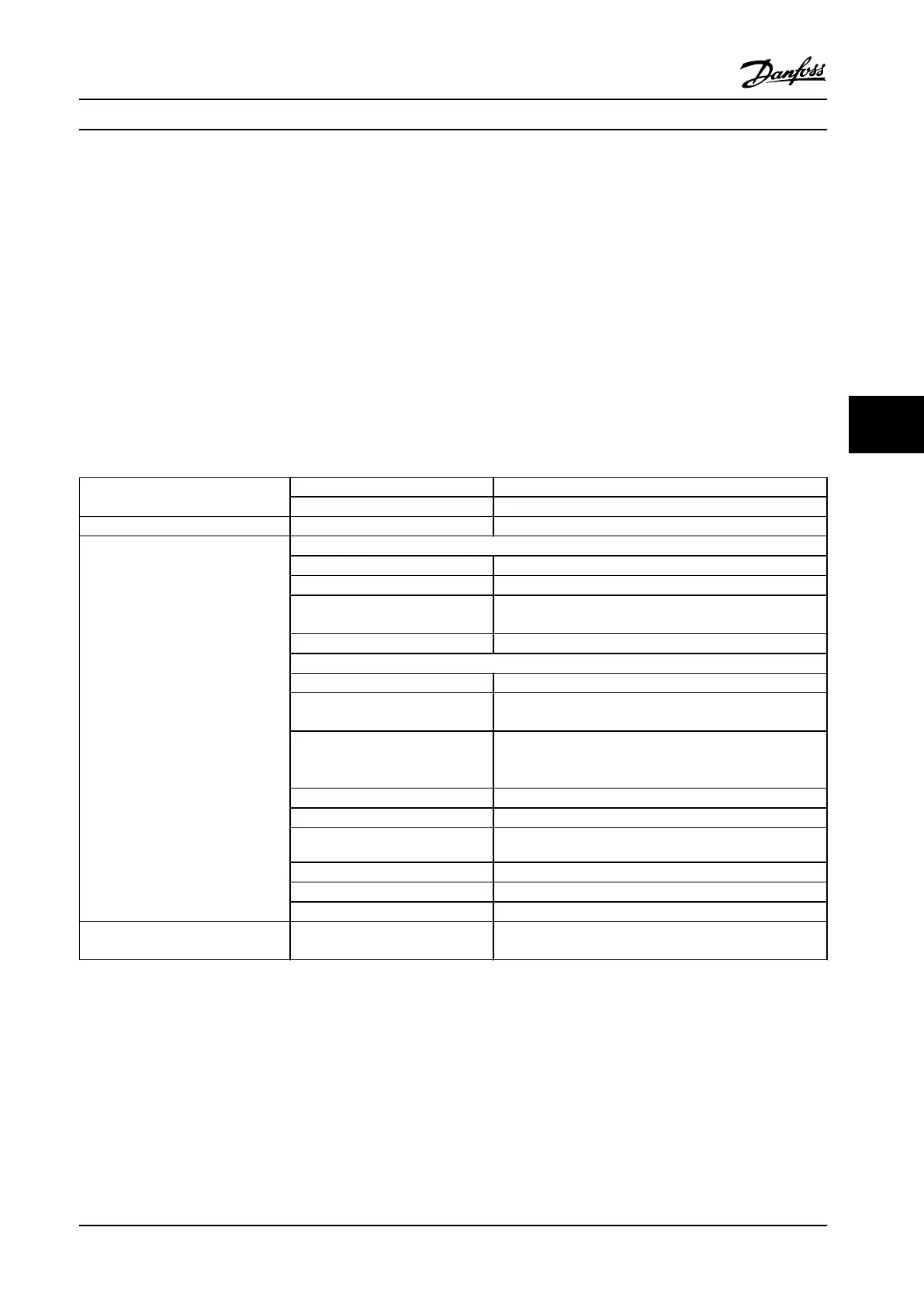
Safety standards
Safety of Machinery ISO 13849-1, IEC 62061
Functional Safety IEC 61508
Safety function Safe Torque O IEC 61800-5-2
Safety performance
ISO 13849-1
Category Cat. 3
Diagnostic Coverage (DC) 60% (Low)
Mean Time to Dangerous Failure
(MTTFd)
2400 years (High)
Performance Level PL d
IEC 61508/IEC 61800-5-2/IEC 62061
Safety Integrity Level SIL2
Probability of Dangerous Failure per
Hour (PFH) (High Demand Mode)
7.54E-9 (1/h)
Probability of Dangerous Failure on
Demand (PFD
avg
for PTI = 20 years)
(Low Demand Mode)
6.05E-4
Safe Failure Fraction (SFF) > 84%
Hardware Fault Tolerance (HFT) 1 (Type A, 1oo2D)
Proof Test Interval
2)
20 Years
Common Cause Failure (CCF) β = 5%; β
D
= 5%
Diagnostic Test Interval (DTI) 160 ms
Systematic Capability SC 2
Reaction time
1)
Input to output response time Enclosure sizes K1–K3: Maximum 50 ms
Enclosure sizes K4 and K5: Maximum 30 ms
Table 6.3 Technical Data for STO
1) Reaction time is the amount of time from an input signal condition that triggers the STO until the torque is o on the motor.
2) For the way to perform proof test, please refer to chapter 6.4 Maintenance and Service for STO.
Safe Torque O (STO) Instruction Manual
MG07A122 Danfoss A/S © 11/2015 All rights reserved. 37
6
6

 Loading...


