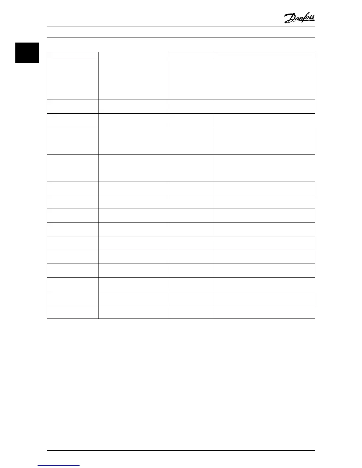
Parameter Range Default Function
1-73 Flying Start [0] Disabled
[1] Enabled
0
Select [1] Enable to enable the drive to catch a
motor spinning due to mains drop-out. Select [0]
Disable if this function is not required. When is
enabled 1-71 Start Delay and 1-72 Função de
Partida have no function. is active in VVC
plus
mode
only
3-02 Minimum Reference -4999-4999 0 The minimum reference is the lowest value
obtainable by summing all references.
3-03 Maximum Reference -4999-4999 50 The maximum reference is the lowest obtainable
by summing all references.
3-41 Ramp 1 Ramp Up
Time
0.05-3600.0 s Size related Ramp up time from 0 to rated 1-23 Motor
Frequency if Asynchron motor is selected; ramp up
time from 0 to 1-25 Motor Nominal Speed if PM
motor is selected.
3-42 Ramp 1 Ramp
Down Time
0.05-3600.0 s Size related Ramp down time from rated 1-23 Motor
Frequency to 0 if Asynchron motor is selected;
ramp down time from 1-25 Motor Nominal Speed
to 0 if PM motor is selected.
4-12 Motor Speed Low
Limit [Hz]
0.0-400 Hz 0 Hz Enter the minimum limit for low speed.
4-14 Motor Speed High
Limit [Hz]
0.0-400 Hz 65 Hz Enter the maximum limit for high speed.
4-19 Freqüência Máx. de
Saída
0-400 Size related Enter the maximum output frequency value.
5-40 Function Relay [0]
Function relay
See 5-40 Function Relay Alarm Select the function to control output relay 1.
5-40 Function Relay [1]
Function relay
See 5-40 Function Relay Drive running Select the function to control output relay 2.
6-10 Terminal 53 Low
Voltage
0-10 V 0.07 V Enter the voltage that corresponds to the low
reference value.
6-11 Terminal 53 High
Voltage
0-10 V 10 V Enter the voltage that corresponds to the high
reference value.
6-12 Terminal 53 Low
Current
0-20 mA 4 Enter the current that corresponds to the low
reference value.
6-13 Terminal 53 High
Current
0-20 mA 20 Enter the current that corresponds to the high
reference value.
6-19 Terminal 53 mode [0] Current
[1] Voltage
1 Select if terminal 53 is used for current- or voltage
input.
Table 1.17 The Start-up Wizard for Open Loop Applications
Quick Guide
VLT
®
HVAC Basic Drive Cascade Controller Quick Guide
16 MG18F402 - VLT
®
is a registered Danfoss trademark
11

 Loading...


