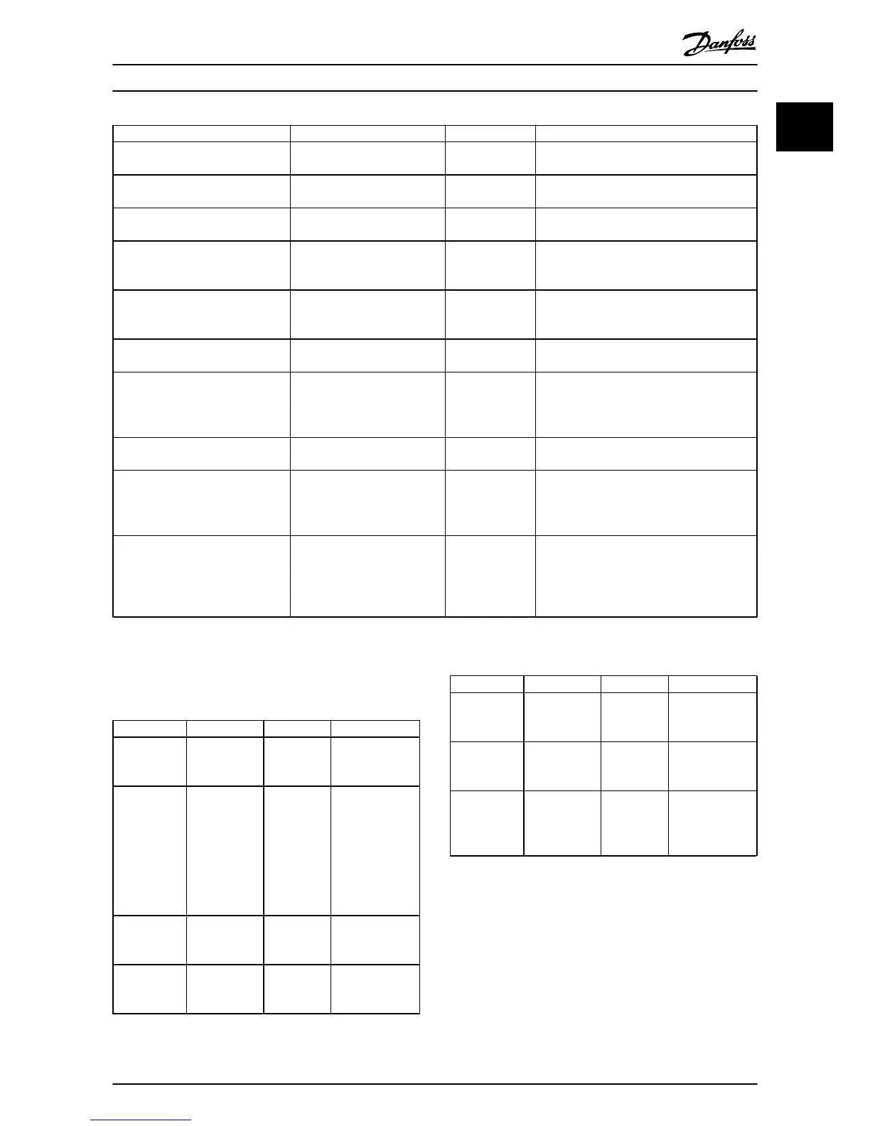
Parameter Range Default Function
6-21 Terminal 54 High Voltage 0-10 V 10 V Enter the voltage that corresponds to the low
high reference value.
6-22 Terminal 54 Low Current 0-20 mA 4 Enter the current that corresponds to the high
reference value.
6-23 Terminal 54 High Current 0-20 mA 20 Enter the current that corresponds to the high
reference value.
6-24 Terminal 54 Low Ref./Feedb.
Value
-4999-4999 0 Enter the feedback value that corresponds to
the voltage or current set in 6-20 Terminal 54
Low Voltage/6-22 Terminal 54 Low Current.
6-25 Terminal 54 High Ref./Feedb.
Value
-4999-4999 50 Enter the feedback value that corresponds to
the voltage or current set in 6-21 Terminal 54
High Voltage/6-23 Terminal 54 High Current.
6-26 Terminal 54 Filter Time
Constant
0-10 s 0.01 Enter the filter time constant.
20-81 PI Normal/ Inverse Control [0] Normal
[1] Inverse
0
Select [0] Normal to set the process control to
increase the output speed when the process
error is positive. Select [1] Inverse to reduce
the output speed.
20-83 PI Start Speed [Hz] 0-200 Hz 0 Enter the motor speed to be attained as a
start signal for commencement of PI control.
20-93 PI Proportional Gain 0-10 0.01 Enter the process controller proportional gain.
Quick control is obtained at high amplifi-
cation. However if amplification is too great,
the process may become unstable.
20-94 PI Integral Time 0.1-999.0 s 999.0 s Enter the process controller integral time.
Obtain quick control through a short integral
time, though if the integral time is too short,
the process becomes unstable. An excessively
long integral time disables the integral action.
Table 1.18 Closed Loop Set-up Wizard
Motor Set-up
The Quick Menu Motor Set-up guides through the needed
motor parameters.
Parameter Range Default Function
0-03 Regional
Settings
[0] Interna-
tional
[1] US
0
0-06 GridType [0] -[132] see
start -up
wizard for
open loop
application
Size selected Select operating
mode for restart
upon
reconnection of
the drive to
mains voltage
after power
down.
1-20 Motor
Power
0.12-110 kW/
0.16-150 hp
Size related Enter motor
power from
nameplate data.
1-22 Motor
Voltage
50.0-1000.0 V Size related Enter motor
voltage from
nameplate data.
Parameter Range Default Function
1-23 Motor
Frequency
20.0-400.0 Hz Size related Enter motor
frequency from
nameplate data.
1-24 Motor
Current
0.01-10000.00
A
Size related Enter motor
current from
nameplate data.
1-25 Motor
Nominal
Speed
100.0-9999.0
RPM
Size related Enter motor
nominal speed
from nameplate
data.
Quick Guide
VLT
®
HVAC Basic Drive Cascade Controller Quick Guide
MG18F402 - VLT
®
is a registered Danfoss trademark 19
1 1

 Loading...


