EXAMPLE 2:
Variable= FEEDBACK, range= -200% to +200%
Range needed for output= 0–100%
Output signal 0 or 4 mA is needed at 0% (50% of range) - set par.6-51
Terminal 42 Output Min Scale
to 50%
Output signal 20 mA is needed at 100% (75% of range) - set par.6-52
Terminal 42 Output Max Scale
to 75%
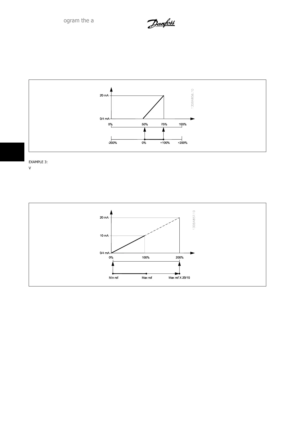
EXAMPLE 3:
Variable value= REFERENCE, range= Min ref - Max ref
Range needed for output= Min ref (0%) - Max ref (100%), 0–10 mA
Output signal 0 or 4 mA is needed at Min ref - set par.6-51
Terminal 42 Output Min Scale
to 0%
Output signal 10 mA is needed at Max ref (100% of range) - set par.6-52
Terminal 42 Output Max Scale
to 200%
(20 mA / 10 mA x 100%=200%).
6 How to program the adjustable frequency
drive
VLT
®
HVAC Drive Instruction Manual
6-42
MG.11.A9.22 - VLT
®
is a registered Danfoss trademark
6