EasyManuals Logo

Danfoss VLT User Manual

Danfoss VLT
179 pages
To Next Page IconTo Next Page
To Previous Page IconTo Previous Page
Page #45 background imageLoading...
Page #45 background image
4.1.25 Control Terminals
Drawing reference numbers:
1. 10-pole plug, digital I/O.
2. 3-pole plug, RS-485 bus.
3. 6-pole, analog I/O.
4. USB connection.
Figure 4.48: Control terminals (all enclosures)
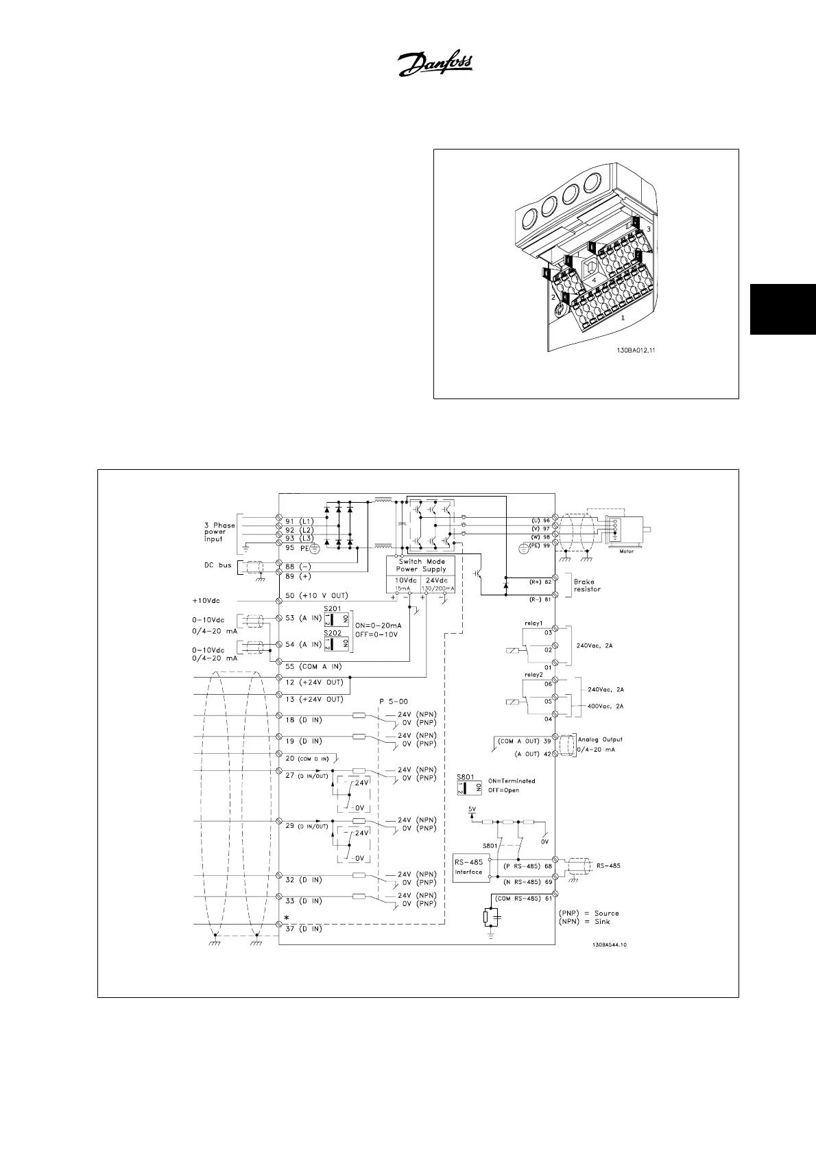
4.1.26 Electrical Installation and Control Cables
Figure 4.49: Diagram showing all electrical terminals. (Terminal 37 present for units with safe stop function only.)
VLT
®
HVAC Drive Instruction Manual 4 Electrical installation
MG.11.A9.22 - VLT
®
is a registered Danfoss trademark
4-27
4

Other manuals for Danfoss VLT

Questions and Answers:

Question and Answer IconNeed help?

Do you have a question about the Danfoss VLT and is the answer not in the manual?

Danfoss VLT Specifications

General IconGeneral
Frequency50/60 Hz
EnclosureIP20, IP21, IP55, IP66
SeriesVLT
Control TechniqueFlux Vector Control
Output Voltage0-Vinput
Control MethodFieldbus
Communication InterfacePROFIBUS, CANopen
Protection FeaturesOverload, Overvoltage, Undervoltage, Short Circuit, Ground Fault
Cooling MethodLiquid Cooled
Storage Temperature-25°C to +70°C
Relative Humidity5-95% non-condensing
AltitudeUp to 1000m (3280ft) without derating, up to 4000m (13120ft) with derating
Operating Temperature-10°C to +50°C (14°F to 122°F)

Related product manuals