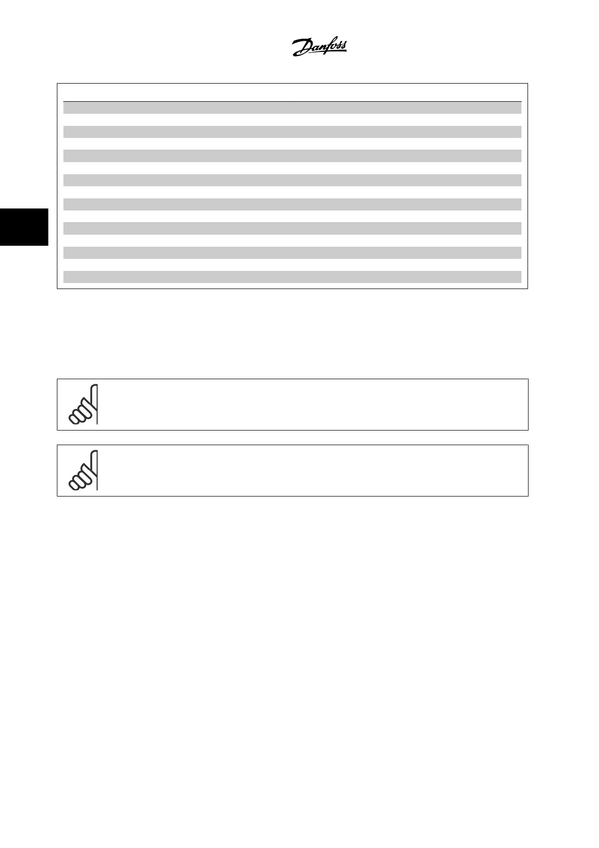
Terminal number Terminal description Parameter number Factory default
1+2+3 Terminal 1+2+3-Relay1 5-40 No operation
4+5+6 Terminal 4+5+6-Relay2 5-40 No operation
12 Terminal 12 Supply - +24 V DC
13 Terminal 13 Supply - +24 V DC
18 Terminal 18 Digital Input 5-10 Start
19 Terminal 19 Digital Input 5-11 No operation
20 Terminal 20 - Common
27 Terminal 27 Digital Input/Output 5-12/5-30 Coast inverse
29 Terminal 29 Digital Input/Output 5-13/5-31 Jog
32 Terminal 32 Digital Input 5-14 No operation
33 Terminal 33 Digital Input 5-15 No operation
37 Terminal 37 Digital Input - Safe Stop
42 Terminal 42 Analog Output 6-50 No operation
53 Terminal 53 Analog Input 3-15/6-1*/20-0* Reference
54 Terminal 54 Analog Input 3-15/6-2*/20-0* Feedback
Table 4.18: Terminal connections
Very long control cables and analog signals may, in rare cases and depending on the installation, result in 50/60 Hz ground loops due to noise from line
power supply cables.
If this occurs, break the shield or insert a 100 nF capacitor between shield and chassis.
NOTE!
The common of digital / analog inputs and outputs should be connected to separate common terminals 20, 39, and 55. This will prevent
ground current interference among groups. For example, it prevents switching on digital inputs from disturbing analog inputs.
NOTE!
Control cables must be shielded/armored.
4.1.27 Switches S201, S202, and S801
Switches S201 (Al 53) and S202 (Al 54) are used to select a current (0-20
mA) or a voltage (0 to 10 V) configuration of the analog input terminals
53 and 54 respectively.
Switch S801 (BUS TER.) can be used to enable termination on the RS-485
port (terminals 68 and 69).
Please note that the switches may be covered by an option, if so equip-
ped.
Default setting:
S201 (AI 53) = OFF (voltage input)
S202 (AI 54) = OFF (voltage input)
S801 (Bus termination) = OFF
4 Electrical installation VLT
®
HVAC Drive Instruction Manual
4-28
MG.11.A9.22 - VLT
®
is a registered Danfoss trademark
4