EasyManuals Logo

Danfoss VLT User Manual

Danfoss VLT
179 pages
To Next Page IconTo Next Page
To Previous Page IconTo Previous Page
Page #47 background imageLoading...
Page #47 background image
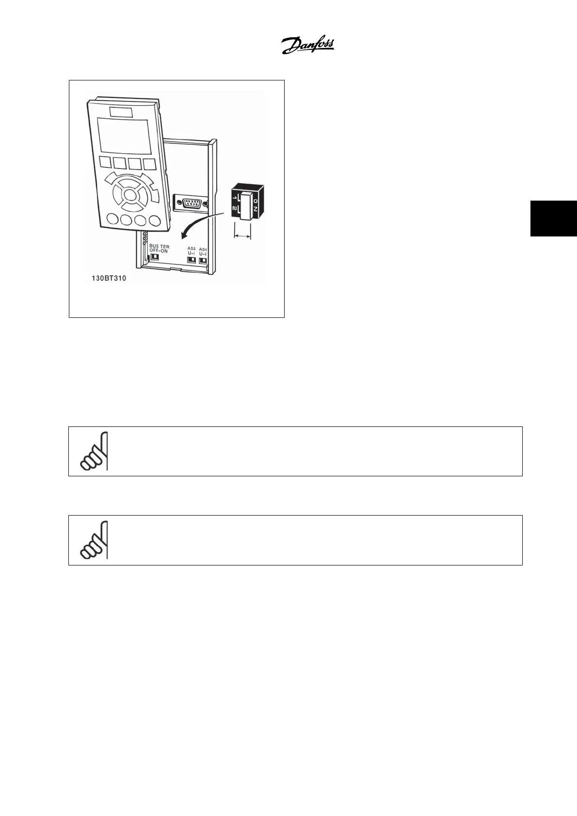
Figure 4.50: Switches location.
4.2 Final optimization and test
4.2.1 Final optimization and test
To optimize motor shaft performance and optimize the adjustable frequency drive for the connected motor and installation, please follow these steps:
Ensure that the adjustable frequency drive and motor are connected and that power is applied to the adjustable frequency drive.
NOTE!
Before power-up, ensure that connected equipment is ready for use.
Step 1. Locate motor nameplate
NOTE!
The motor is either star- (Y) or delta-connected (Δ). This information is located on the motor nameplate data.
VLT
®
HVAC Drive Instruction Manual 4 Electrical installation
MG.11.A9.22 - VLT
®
is a registered Danfoss trademark
4-29
4

Other manuals for Danfoss VLT

Questions and Answers:

Question and Answer IconNeed help?

Do you have a question about the Danfoss VLT and is the answer not in the manual?

Danfoss VLT Specifications

General IconGeneral
Frequency50/60 Hz
EnclosureIP20, IP21, IP55, IP66
SeriesVLT
Control TechniqueFlux Vector Control
Output Voltage0-Vinput
Control MethodFieldbus
Communication InterfacePROFIBUS, CANopen
Protection FeaturesOverload, Overvoltage, Undervoltage, Short Circuit, Ground Fault
Cooling MethodLiquid Cooled
Storage Temperature-25°C to +70°C
Relative Humidity5-95% non-condensing
AltitudeUp to 1000m (3280ft) without derating, up to 4000m (13120ft) with derating
Operating Temperature-10°C to +50°C (14°F to 122°F)

Related product manuals