4 Electrical installation
4.1 How to connect
4.1.1 Cables General
NOTE!
For the VLT HVAC Drive High Power series line power and motor connections, please see the VLT HVAC Drive
High Power Instruction
ManualMG.11.FX.YY
.
NOTE!
Cables General
All cabling must comply with national and local regulations on cable cross-sections and ambient temperature. Copper (140°–167°F
[60°–75°C]) conductors are recommended.
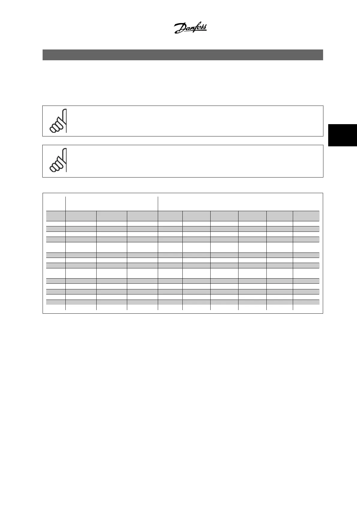
Details of terminal tightening torques.
Power (kW) Torque (Nm)
Enclo-
sure
200–240
V
380–480
V
525–600
V
Line pow-
er
Motor
DC connec-
tion
Brake Ground Relay
A2 1.1–3.0 1.1–4.0 1.8 1.8 1.8 1.8 3 0.6
A3 3.7 5.5–7.5 1.1–7.5 1.8 1.8 1.8 1.8 3 0.6
A5 1.1–3.7 1.1–7.5 1.1–7.5 1.8 1.8 1.8 1.8 3 0.6
B1 5.5–11 11–18.5 - 1.8 1.8 1.5 1.5 3 0.6
B2
-
15
22
30
-
-
4.5
4.5
2)
4.5
4.5
2)
3.7
3.7
3.7
3.7
3
3
0.6
0.6
B3 5.5–11 11–18.5 11–18.5 1.8 1.8 1.8 1.8 3 0.6
B4 11–18.5 18.5–37 18.5–37 4.5 4.5 4.5 4.5 3 0.6
C1 18.5–30 37 - 55 - 10 10 10 10 3 0.6
C2 37 - 45 75 - 90
-
-
14/24
1)
14/24
1)
14 14 3 0.6
C3 18.5–30 37 - 55 37 - 55 10 10 10 10 3 0.6
C4 30 - 45 55 - 90 55 - 90
14/24
1)
14/24
1)
14 14 3 0.6
D1/D3 - 110 - 132 110 - 132 19 19 9.6 9.6 19 0.6
D2/D4 - 160-250 160-315 19 19 9.6 9.6 19 0.6
E1/E2 - 315-450 355-560 19 19 19 9.6 19 0.6
F1–F4
3)
-
Table 4.1: Tightening of terminals
1) For different cable dimensions x/y, where x ≤0.147 in² [95 mm²] and y≥0.147 in² [95 mm²]
2) Cable dimensions above 25 hp [18.5 kW] ≥ 0.0542 in
2
[35 mm
2
] and below 30 hp [22 kW] ≤ 0.0155 in
2
[10 mm
2
]
3) For data on the F-series, please consult VLT
®
HVAC Drive High Power Instruction Manual, MG.11.F1.02
4.1.2 Fuses
Branch circuit protection
In order to protect the installation against electrical and fire hazard, all branch circuits in an installation, switch gear, machines, etc., must be short-circuit
and overcurrent protected according to the national/international regulations.
Short circuit protection
The adjustable frequency drive must be protected against short-circuit to avoid electrical or fire hazard. Danfoss recommends using the fuses mentioned
below to protect service personnel or other equipment in case of an internal failure in the unit. The adjustable frequency drive provides full short circuit
protection in case of a short circuit in the motor output.
VLT
®
HVAC Drive Instruction Manual 4 Electrical installation
MG.11.A9.22 - VLT
®
is a registered Danfoss trademark
4-1
4