EasyManuals Logo

Danfoss VLT User Manual

Danfoss VLT
179 pages
To Next Page IconTo Next Page
To Previous Page IconTo Previous Page
Page #34 background imageLoading...
Page #34 background image
4.1.15 Motor connection for B3 and B4
Figure 4.20: First terminate the motor ground, then place
motor U, V and W wires in the terminal and tighten them.
Please ensure that the outer insulation of the motor cable is
removed under the EMC clamp.
Figure 4.21: First terminate the motor ground, then place
motor U, V and W wires in the terminal and tighten them.
Please ensure that the outer insulation of the motor cable is
removed under the EMC clamp.
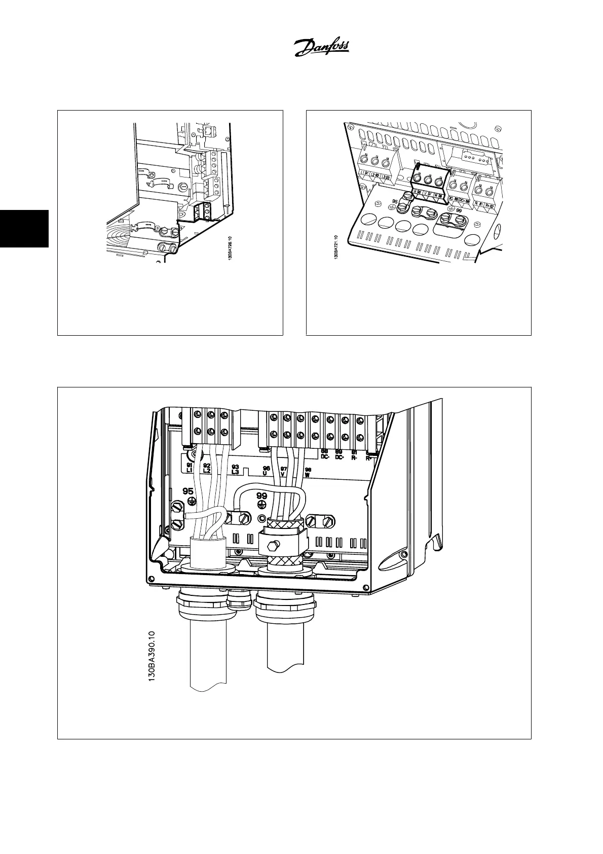
4.1.16 Motor connection for C1 and C2
Figure 4.22: First terminate the motor ground, then place motor U, V and W wires in the terminal and tighten them. Please ensure that the
outer insulation of the motor cable is removed under the EMC clamp.
4 Electrical installation VLT
®
HVAC Drive Instruction Manual
4-16
MG.11.A9.22 - VLT
®
is a registered Danfoss trademark
4

Other manuals for Danfoss VLT

Questions and Answers:

Question and Answer IconNeed help?

Do you have a question about the Danfoss VLT and is the answer not in the manual?

Danfoss VLT Specifications

General IconGeneral
Frequency50/60 Hz
EnclosureIP20, IP21, IP55, IP66
SeriesVLT
Control TechniqueFlux Vector Control
Output Voltage0-Vinput
Control MethodFieldbus
Communication InterfacePROFIBUS, CANopen
Protection FeaturesOverload, Overvoltage, Undervoltage, Short Circuit, Ground Fault
Cooling MethodLiquid Cooled
Storage Temperature-25°C to +70°C
Relative Humidity5-95% non-condensing
AltitudeUp to 1000m (3280ft) without derating, up to 4000m (13120ft) with derating
Operating Temperature-10°C to +50°C (14°F to 122°F)

Related product manuals