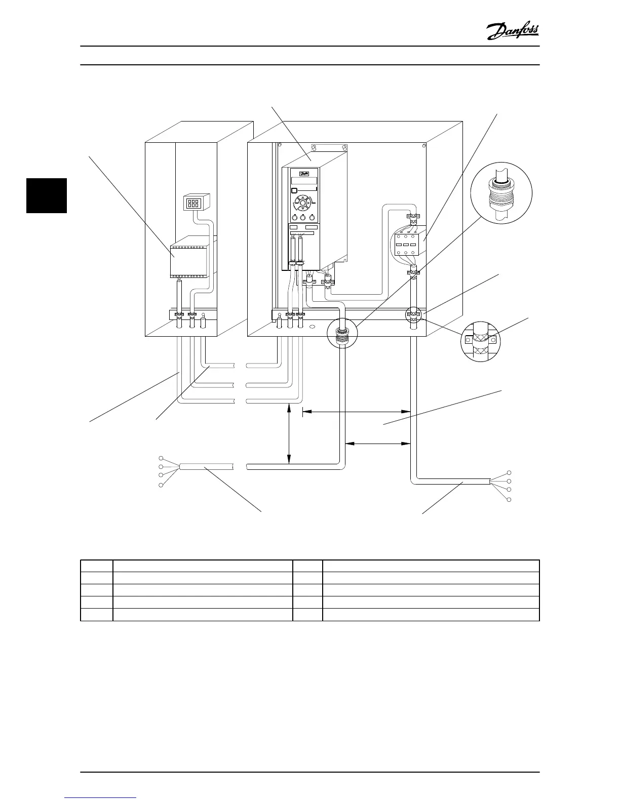
Illustration 3.2 Typical Electrical Connection
1
PLC 6 Min. 200 mm (7.9 in) between control cables, motor and mains
2 Frequency converter 7 Motor, 3-phase and PE
3 Output contactor (Generally not recommended) 8 Mains, 3-phase and reinforced PE
4 Earth (grounding) rail (PE) 9 Control wiring
5 Cable insulation (stripped) 10
Equalising min. 16 mm
2
(0.025 in)
Table 3.2
Installation
VLT
®
AutomationDrive FC 360 Quick Guide
12 MG06A102 - VLT
®
is a registered Danfoss trademark
33
 Loading...


