EasyManuals Logo

Danfoss VLTAutomationDrive FC 360 User Manual

Danfoss VLTAutomationDrive FC 360
52 pages
To Next Page IconTo Next Page
To Previous Page IconTo Previous Page
Page #15 background imageLoading...
Page #15 background image
3.2 Electrical Installation
This section contains detailed instructions for wiring the frequency converter.
130BC438.11
3 Phase
power
input
Switch Mode
Power Supply
Motor
Analog Output
Interface
relay1
(PNP) = Source
(NPN) = Sink
ON=Terminated
OFF=Open
Brake
resistor
91 (L1)
92 (L2)
93 (L3)
PE
50 (+10 V OUT)
53 (A IN)
54 (A IN)
55 (COM A IN)
0/4-20 mA
12 (+24V OUT)
31 (D IN)
18 (D IN)
20 (COM D IN)
10Vdc
15mA 100mA
+ - + -
(U) 96
(V) 97
(W) 98
(PE) 99
(A OUT) 45
(A OUT) 42
(P RS-485) 68
(N RS-485) 69
(COM RS-485) 61
0V
5V
S801
0/4-20 mA
RS-485
RS-485
03
+10Vdc
0/4-20 mA
0-10V dc
240Vac, 2A
24Vdc
02
01
05
04
240Vac, 2A
24V (NPN)
0V (PNP)
0V (PNP)
24V (NPN)
19 (D IN)
24V (NPN)
0V (PNP)
27
24V
0V
(D IN/OUT)
0V (PNP)
24V (NPN)
(D IN/OUT)
0V
24V
29
24V (NPN)
0V (PNP)
0V (PNP)
24V (NPN)
33 (D IN)
32 (D IN)
95
P 5-00
21
ON
(+UDC) 82
(BR) 81
24V (NPN)
0V (PNP)
0-10V dc
(-UDC) 88
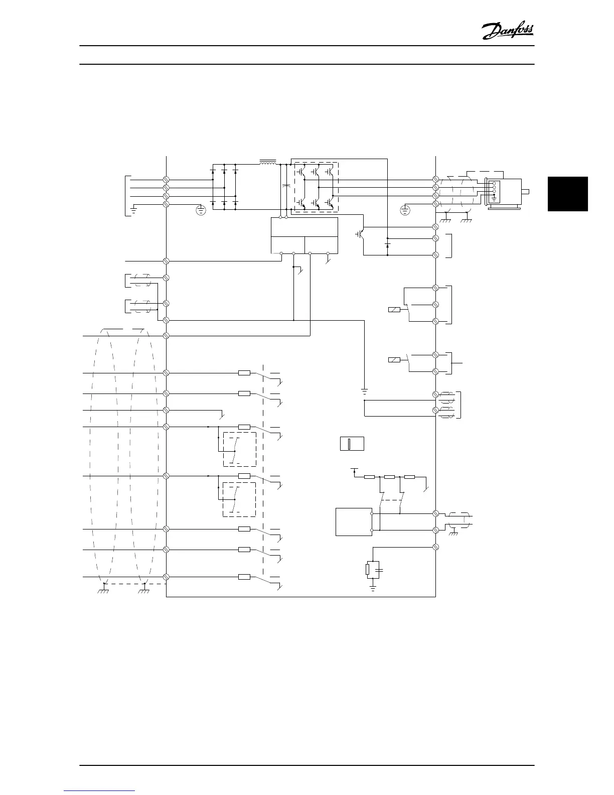
Illustration 3.1 Basic Wiring Schematic Drawing
A=Analog, D=Digital
1) Built-in braking chopper available from 0.37 - 22 kW
2) Relay 2 is 2 pole for J1-J3 and 3 pole for J4-J7. Relay 2 of J4-J7 with terminal 4,5,6, same NO/NC logic as Relay 1.
Installation
VLT
®
AutomationDrive FC 360 Quick Guide
MG06A102 - VLT
®
is a registered Danfoss trademark 11
3 3

Questions and Answers:

Question and Answer IconNeed help?

Do you have a question about the Danfoss VLTAutomationDrive FC 360 and is the answer not in the manual?

Danfoss VLTAutomationDrive FC 360 Specifications

General IconGeneral
BrandDanfoss
ModelVLTAutomationDrive FC 360
CategoryController
LanguageEnglish

Related product manuals