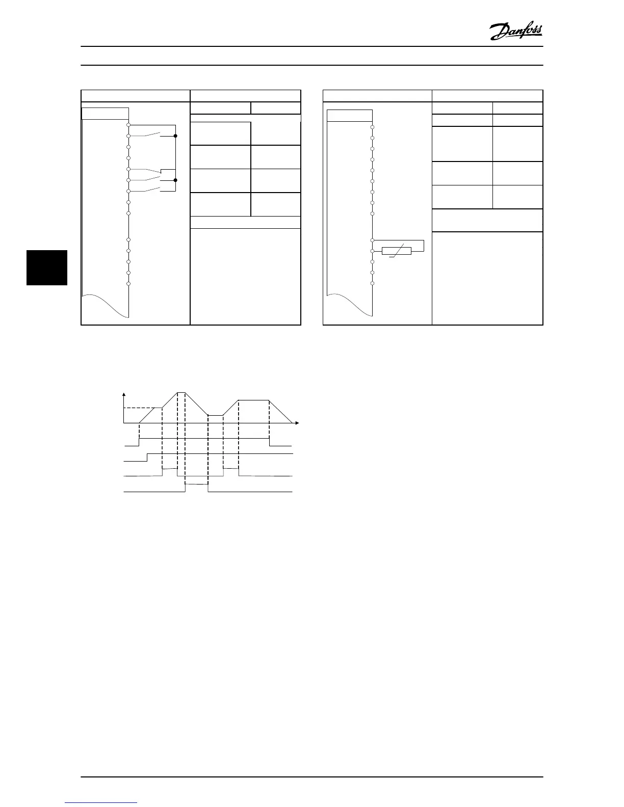
EasyManua.ls Logo

Danfoss VLTAutomationDrive FC 360

Danfoss VLTAutomationDrive FC 360
52 pages
To Next Page IconTo Next Page
To Previous Page IconTo Previous Page
Loading...
Parameters
Function Setting
5-10 Terminal 18
Digital Input
[8] Start*
5-12 Terminal 27
Digital Input
[19] Freeze
Reference
5-13 Terminal 29
Digital Input
[21] Speed
Up
5-14 Terminal 32
Digital Input
[22] Speed
Down
* = Default Value
Notes/comments:
Table 5.8 Speed Up/Down
S t a r t ( 1 8 )
F r e e z e r e f ( 2 7 )
S p e e d u p ( 2 9 )
S p e e d d o w n ( 3 2 )
S p e e d
R e f e r e n c e
130BB840.10
Illustration 5.1
CAUTION
Thermistors must use reinforced or double insulation to
meet PELV insulation requirements.
Parameters
Function Setting
1-90 Motor
Thermal
Protection
[2]
Thermistor
trip
1-93 Thermistor
Source
[1] Analog
input 53
6-19 Terminal 53
Mode
[1] Voltage
* = Default Value
Notes/comments:
If only a warning is desired,
1-90 Motor Thermal Protection
should be set to [1] Thermistor
warning.
Table 5.9 Motor Thermistor
Wiring Examples
VLT
®
AutomationDrive FC 360 Quick Guide
30 MG06A102 - VLT
®
is a registered Danfoss trademark
5
5

Related product manuals