Pulse frequency range 4-32 kHz
(Duty cycle) Min. pulse width 4.5 ms
Input resistance, R
i
approx. 4 kΩ
Analog Inputs
Number of analog inputs 2
Terminal number 53, 54
Modes Voltage or current
Mode select software
Voltage mode
Voltage level 0 to +10 V
Input resistance, R
i
approx. 10 kΩ
Max. voltage -15 to + 20 V
Current mode
Current level 0/4 to 20 mA (scaleable)
Input resistance, R
i
approx. 200 Ω
Max. current 30 mA
Resolution for analog inputs 11 bit (+ sign)
Accuracy of analog inputs Max. error 0.5% of full scale
Bandwidth 100 Hz
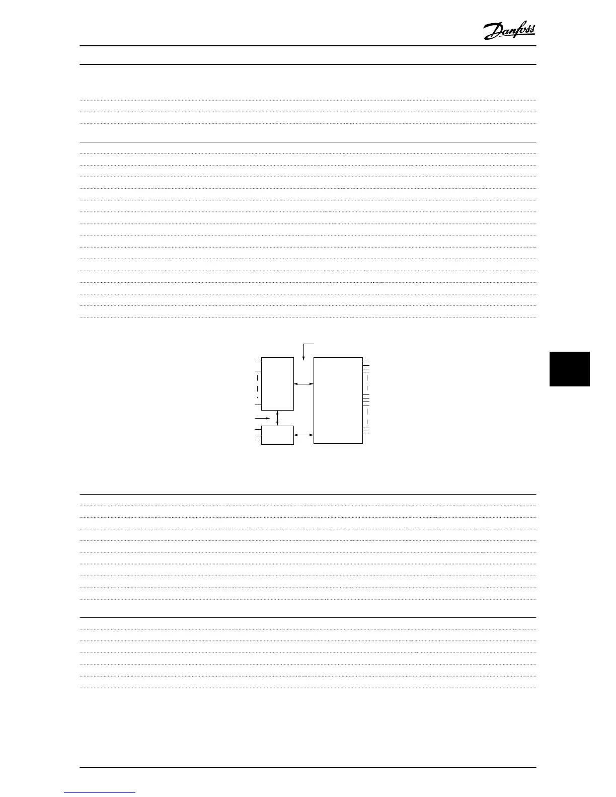
The analog inputs are galvanically isolated from the supply voltage (PELV) and other high-voltage terminals.
Illustration 8.1
Pulse Inputs
Programmable pulse inputs 2
Terminal number pulse 32, 33
Max. frequency at terminal, 29, 33 32 kHz (Push-pull driven)
Max. frequency at terminal, 29, 33 5 kHz (open collector)
Min. frequency at terminal 29, 33 4 Hz
Voltage level see section on Digital input
Maximum voltage on input 28 V DC
Input resistance, R
i
approx. 4 kΩ
Pulse input accuracy (0.1-1 kHz) Max. error: 0.1% of full scale
Analog Outputs
Number of programmable analog outputs 2
Terminal number 45, 42
Current range at analog output 0/4-20 mA
Max. resistor load to common at analog output 500 Ω
Accuracy on analog output Max. error: 0.8 % of full scale
Resolution on analog output 10 bit
The analog output is galvanically isolated from the supply voltage (PELV) and other high-voltage terminals.
Specifications
VLT
®
AutomationDrive FC 360 Quick Guide
MG06A102 - VLT
®
is a registered Danfoss trademark 39
8 8
 Loading...


