APP-control v10.x
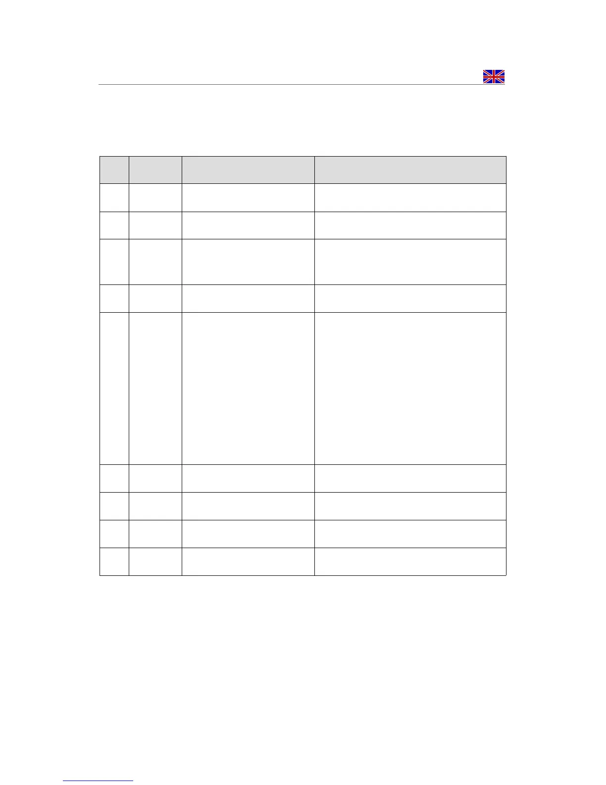
10 Inputs and Outputs (connector I)
PIN color description function
1 yellow Switching output 1 W-BUS, E-BUS
2 black Switching output 2 Output +12V, max. 1A
3 purple Switching output 3 ground, max. 500mA
4 output GND output GND 1KOhm for ext. LED
5 green input +12V Input for ext. button / switch
Button: one impulse (approx. 1s) is
turning the Switching outputs
alternately on and off ("on" for
preset time)
Switch: as long as +12V are applied
the Switching outputs are activated
(max. for preset time)
6 output +12V output +12V for ext. Taster
7 red power supply • +12V (fuse with 5A)
8 brown ground • Ground connection
9 not in uses
14 - 32